POS MV V4 User Guide
Installation
Copyright © Applanix Corporation, 2009
2-30
GND reference connected to Isolated Event 1 Signal Return
(pin 7). For Event 2, the output must be connected to the
Isolated Event 2 (pin 3) with the GND reference connected to
Isolated Event 2 Signal Return (pin 8). Outputs from most of
the 5 V TTL Logic CMOS devices belong to this group and
can directly drive the isolated event inputs.
• Type II event generator with an open collector or open drain
type output capable of sinking (sourcing) a current of 5 - 10
mA. For Event 1, the output must be connected to the
Isolated Event 1 Signal Return (pin 7) with the +5 Vdc source
connected to the Isolated Event 1 (pin 2). For Event 2, the
output must be connected to the Isolated Event 2 Signal
Return (pin 8) with the +5 Vdc source connected to the
Isolated Event 2 (pin 3). Standard TTL or TTL LS devices
with open collector outputs belong to this group.
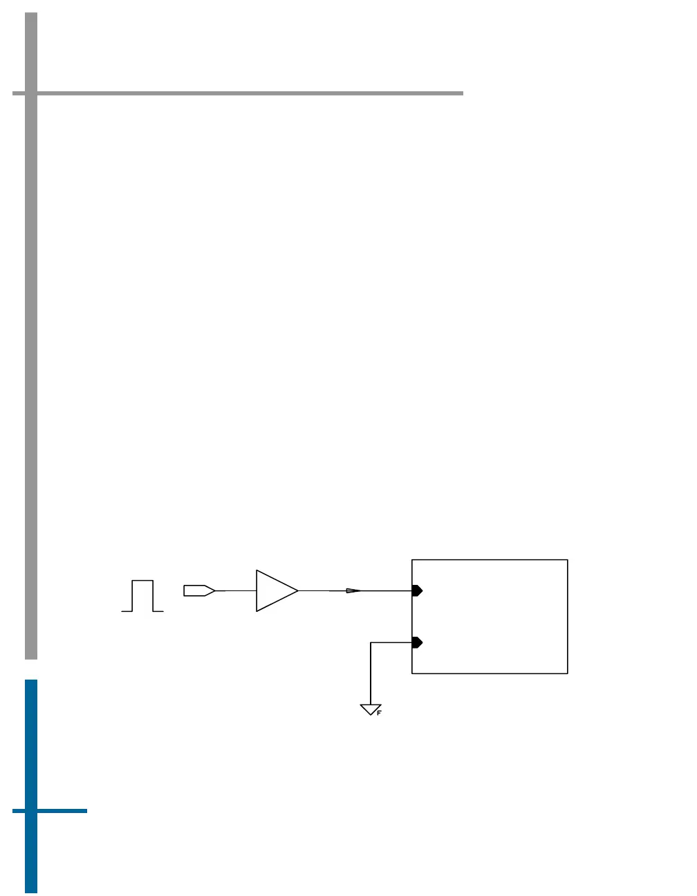
3. The following four Figures demonstrate the possible configurations for
the Event 1 and Event 2 inputs.
EVENT 1 IN
EVENT 1 IN RETURN
74HC4050
1 2
min. 5 mA
EVENT PULSE
Figure 10: Type I Event Generator - I/O Configuration