POS MV V4 User Guide
Installation
Copyright © Applanix Corporation, 2009
2-26
COM (1) through COM (5) Interface
PHYSICAL INTERFACE
Serial cables should not exceed 15 m [~49 ft] in length. To ensure data
integrity, use high quality RS-232 cable with its shielding connected through
the back shell to ground at both cable ends.
Table 5, page 2-23 (POS MV V4-
1) or
Table 6 (POS MV V4) provides connector pin assignments and
mapping.
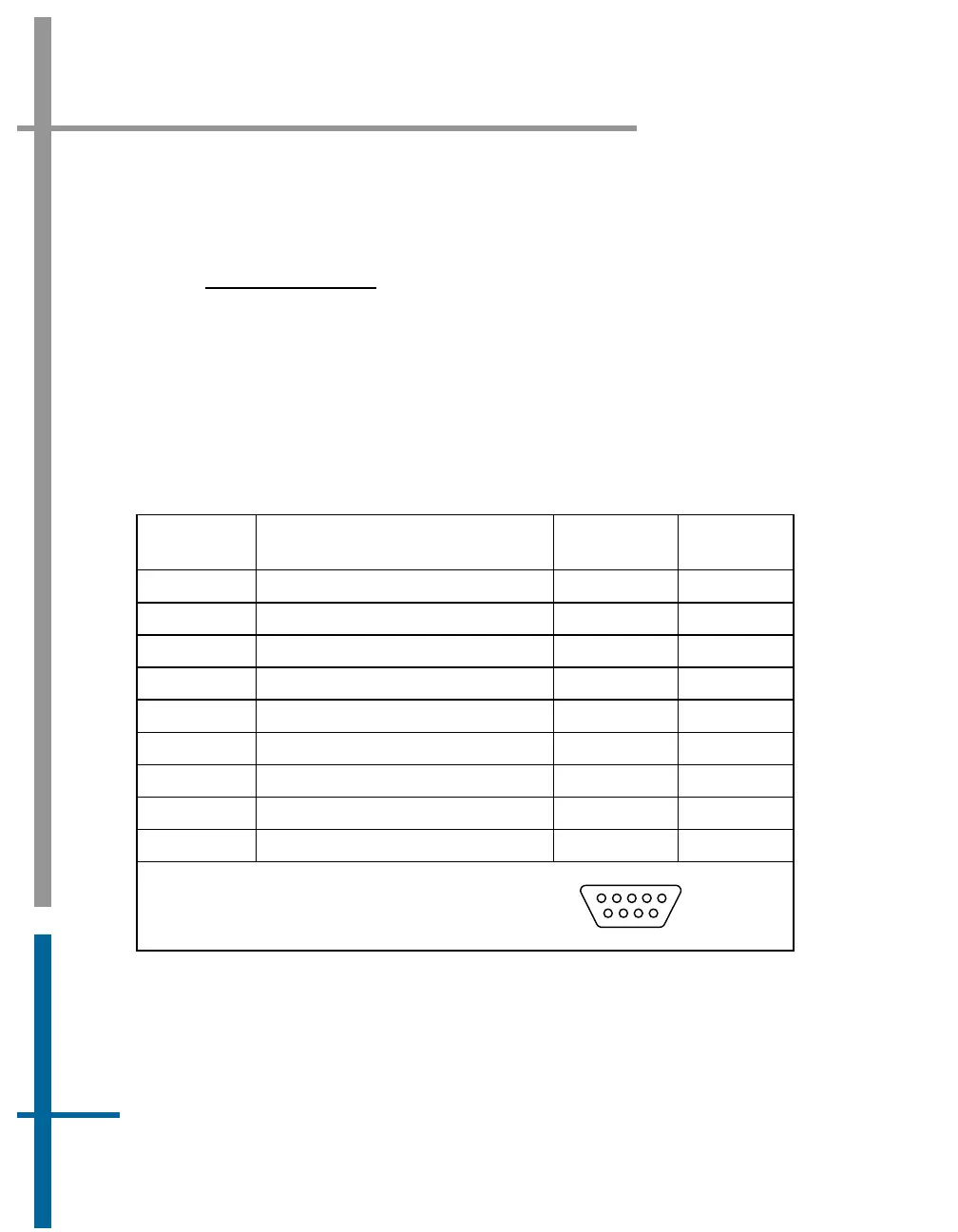
Table 6: COM Connectors Pin Assignment - POS MV V4
Pin Pin Description Signal Type
Signal
Direction
1 N/C (port 1 through 5) N/A N/A
2 RX (port 1 through 5) RS-232 Input
3 TX (port 1 through 5) RS-232 Output
4 DTR (port 1 through 5) RS-232 Output
5 GND (port 1 through 5) N/A N/A
6 DSR (port 1 through 5) RS-232 Input
7 RTS (port 1 through 5) RS-232 Output
8 CTS (port 1 through 5) RS-232 Input
9 N/C (port 1 through 5) N/A N/A
POS MV V4 Rear Panel
DB-9P Male Connector
1
5
6
9