POS MV V4 User Guide
Installation
Copyright © Applanix Corporation, 2009
2-32
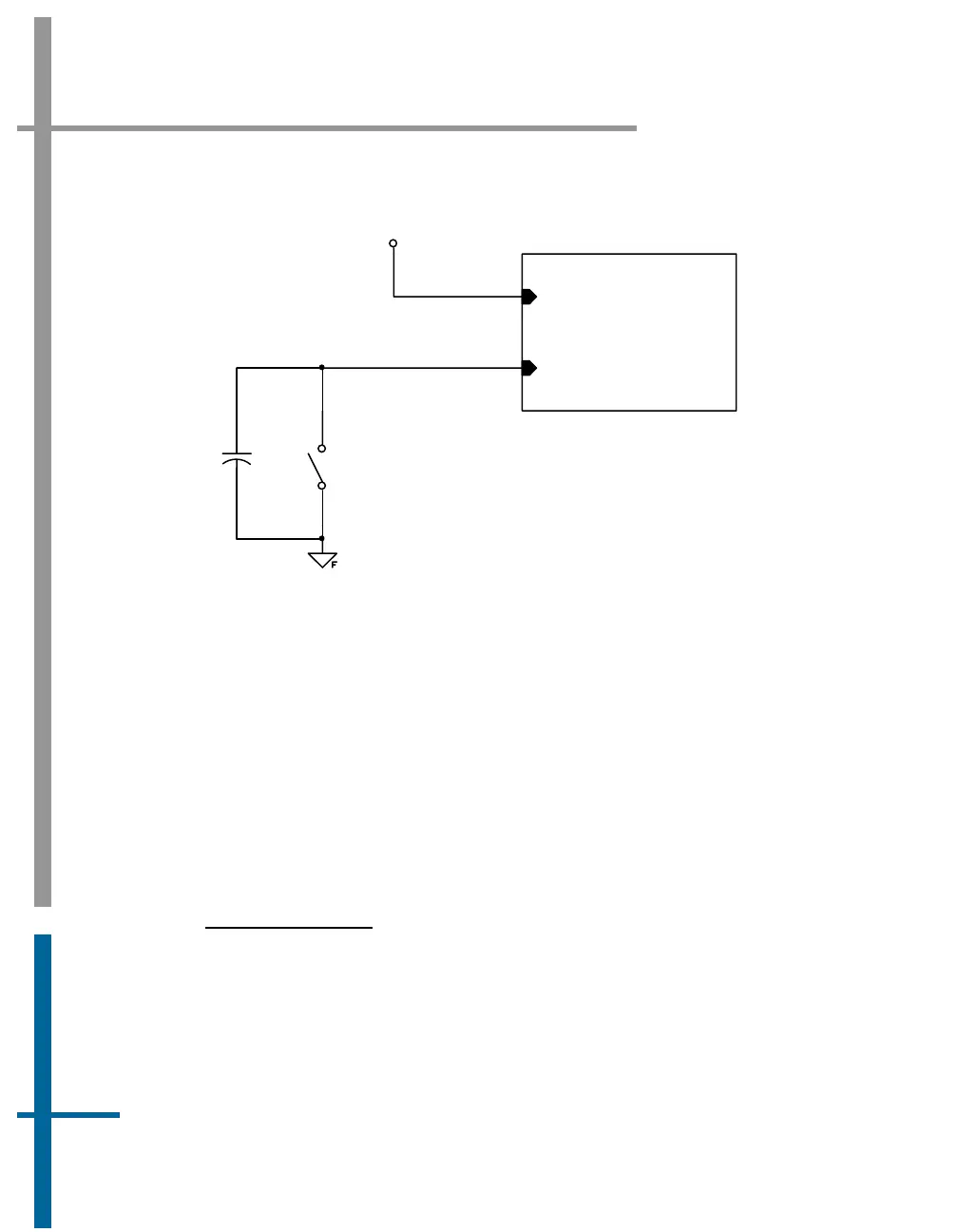
EVENT 1 IN
EVENT 1 IN RETURN
+5VDC
NORMALLY OPEN SWITCH
CLOSE TO GENERATE THE EVENT PULSE
1uF
Figure 13: Mechanical Switch Event Generator - I/O Configuration
4. Event 1 and Event 2 inputs (and their return lines) are un-referenced
and are independent of any internal PCS power supplies or GND.
5. Each isolated Event input must be driven from a separate source.
6. Applanix can provide an events interface box for the event generators
(except for Type I and Type II described above). This events interface
box produces the proper PCS event input signals from devices that
output pulses ranging from 3.3 V to 12 V TTL. Please contact
Applanix Customer Support (page A-1) for more information.
I
NPUT DATA FORMAT
Tagging an event requires one of the following conditions at the input to
the Event digital port:
• 5 - 10 mA current pulse between pins 2 and 7 (rising or falling
edge coincided with the event occurrence) for Event 1


 To Next Page