POS MV V4 User Guide
Installation
Copyright © Applanix Corporation, 2009
2-17
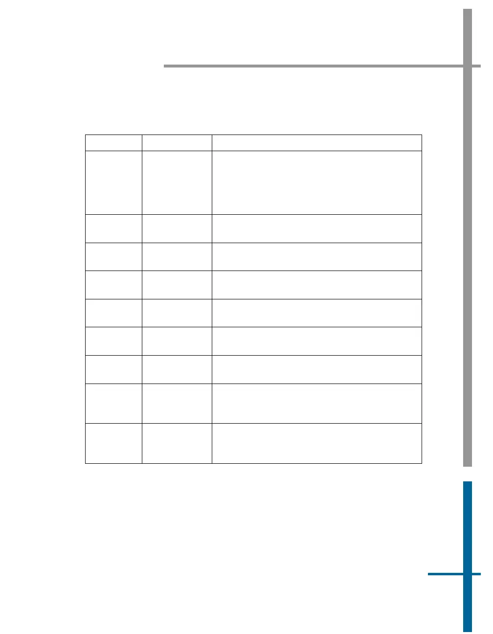
Table 2: Connector/Cable Summary - POS MV V4
Connector Cable Description
GNSS2
(secondary
GNSS
receiver),
DB-9P
Single-
shielded cable
• RS-232 Serial I/P port (digital)
• I/P secondary GNSS receiver software
upgrade - contact Applanix Customer
Support for details
422, DB-9P Single-
shielded cable
Not implemented
COM(1),
DB-9P
Single-
shielded cable
RS-232 Serial I/O port (digital)
COM(2),
DB-9P
Single-
shielded cable
RS-232 Serial I/O port (digital)
COM(3),
DB-9P
Single-
shielded cable
RS-232 Serial I/O port (digital)
COM(4),
DB-9P
Single-
shielded cable
RS-232 Serial I/O port (digital)
COM(5),
DB-9P
Single-
shielded cable
RS-232 Serial I/O port (digital)
ANT1, TNC
female
50 ohm
coaxial cable
(RG303/U)
Supplies dc power to and receives signals
from primary GNSS antenna
ANT2, TNC
female
50 ohm
coaxial cable
(RG303/U)
supplies dc power to and receives signals
from secondary GNSS antenna
If the POS MV V4 receives power from an Uninterruptible Power Supply
(UPS), make certain that it is operating at the correct voltage; refer to the
Power Requirements description on page 2-4 for details. Good grounding
practices are essential for proper operation of the POS MV V4 systems.