EN – 8
IMPORTANT: Discharge chute control designs differ based
on serial number. Generation 2 chute control designs
appear as shown in Figure 4 and Generation 3 chute
control designs appear as shown in Figure 5. Continue to
step 7 for service to units with Generation 2 designs and
advance to step 11 for service to units with Generation 3
designs.
Generation 2 Chute Control Designs
See Figure 4.
7. Remove hairpin and cable eyelet from chute control
assembly.
8. With a pliers, compress cable anchor tabs and remove
anchor from chute control assembly.
9. Guide cable end through hole in dash panel.
IMPORTANT: Reinstall hairpin into clevis pin so it is not
misplaced.
10. Advance to step 16.
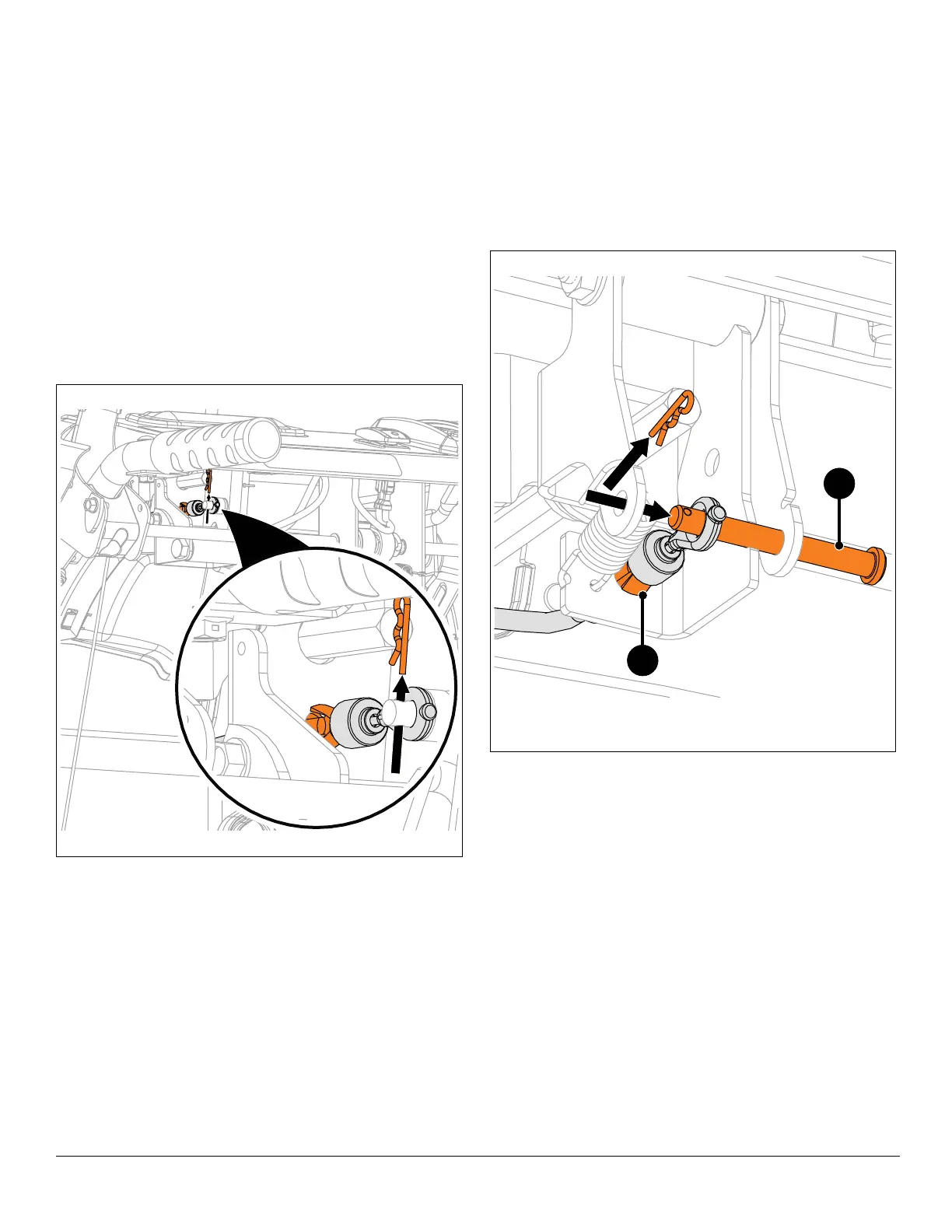
Generation 3 Chute Control Designs
See Figure 5.
11. Remove hairpin from clevis pin and partially remove
clevis pin from chute control assembly.
12. With a pliers, compress cable anchor tabs and remove
anchor from chute control assembly.
13. Guide cable end through hole in dash panel.
IMPORTANT: Reinstall hairpin into clevis pin so it is not
misplaced.
Figure 4
Generation 2 Chute Control Design
Figure 5
1. Cable Anchor
2. Clevis Pin
1
2
Generation 3 Chute Control Design