Manual, F/T Sensor, Ethernet Axia
Document #9610-05-Ethernet Axia-09
Pinnacle Park • 1031 Goodworth Drive • Apex, NC 27539 • Tel:+1 919.772.0115 • Fax:+1 919.772.8259 • www.ati-ia.com
42
11. On the left side of the page is a menu bar with buttons that link to various Ethernet Axia webpages. Click
on the Communications button.
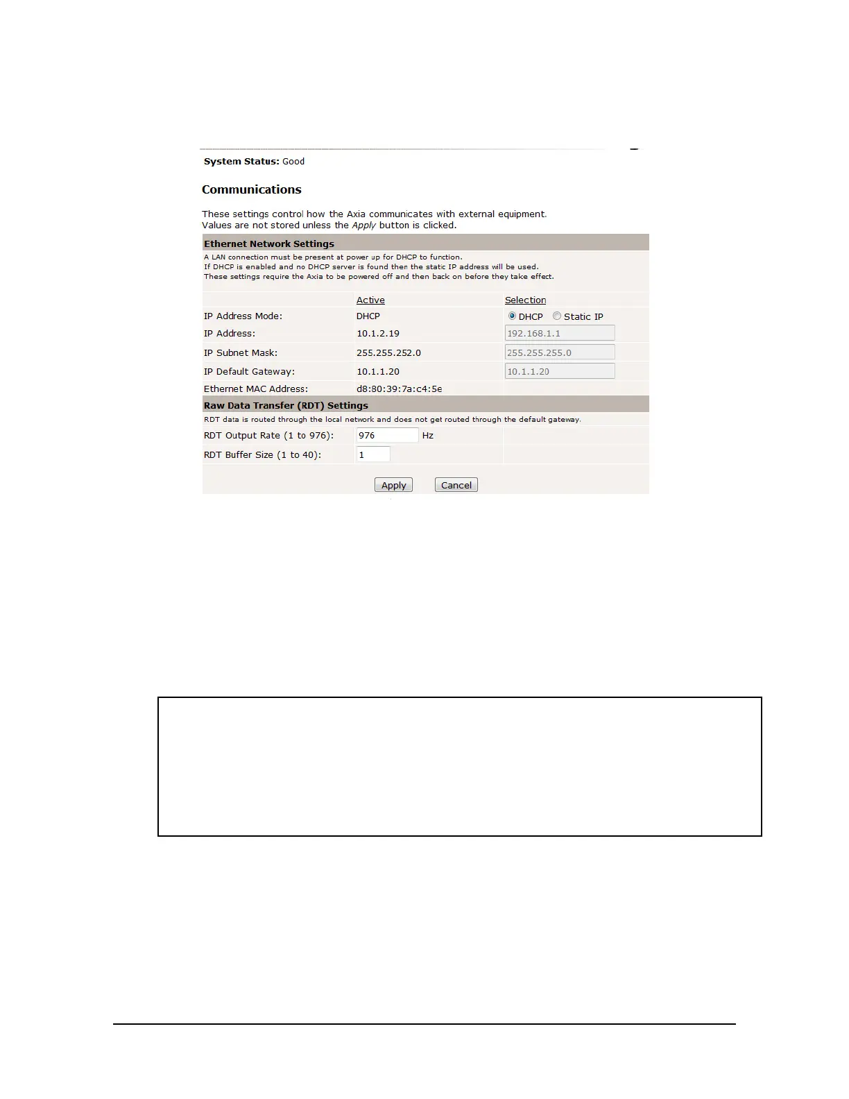
Figure 5.3—The Ethernet Axia F/T Sensor Communications Page
12. Select an IP address mode:
• For a static IP address, enter the appropriate values for the IP address, subnet mask, and default
gateway. Click the Apply button. Power cycle the sensor.
• For DHCP, click the Enabled radio button next to DHCP, and then click the Apply button at the
bottom of the page. Power cycle the sensor. If the sensor does not receive an IP address within 30
seconds after power up, the sensor defaults to use the static IP settings.
• Find the IP address assigned to the sensor. (refer to Section 5.3—Finding the Ethernet Axia
Sensor on a Network)
NOTICE:
• When assigned by a DHCP server, IP addresses are not permanent and may change if the
Ethernet Axia Sensor is disconnected from the network for a period of time. Users should
contact their IT department in this situation. Static IP addresses are more favorable in
permanent Ethernet F/T applications, because the IP address does not change.
• ForacompletedescriptionoftheeldsontheCommunications page, refer to
Section6.6—F/TCongurationsPage(cong.htm).
13. Open up the TCP/IP properties of the local area connection of the computer.
a. If the sensor was set to DHCP and the user’s network has a DHCP server: restore the settings to
what they were before recongured (use the values that were recorded in step 3).
b. If the sensor was set to a static IP address or the network does not have a DHCP server: change
the settings to an IP address on the same local subnet as the sensor. The rst three elds of the IP
address must be the same, but the last eld must be unique. For example, if the sensor was set to
10.1.16.20, the computer can be set to 10.1.16.48 or 10.1.16.123.
 Loading...
