ATI Series D12 Toxic Gas Transmitter with H10 Smart Sensor
Revision N (7/15) 12
ELECTRICAL CONNECTIONS
Board Stack
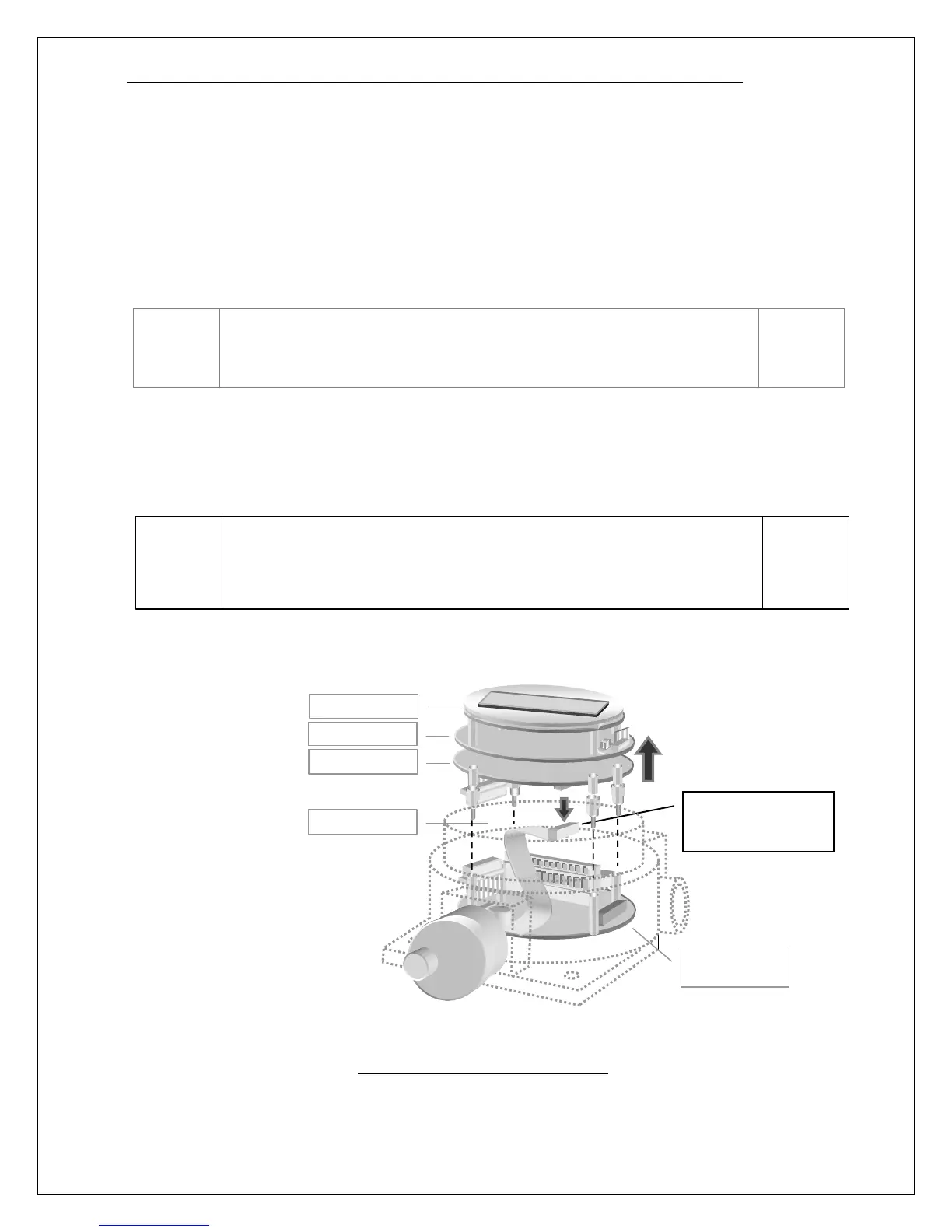
The transmitter consists of four circuit boards, known collectively as the “stack”. From top to bottom,
they are the, Display, CPU, Isolation, and Power Supply boards. The top three boards, Display, CPU,
and Isolation, are fastened together with metal standoffs, and plug into the Power Supply board, which
is fastened to the lower housing with similar metal standoffs. Since most external wiring connections
are made to terminals on the Power Supply board, it will be necessary to remove the top three boards.
To remove the top boards, unscrew the transmitter housing cover and turn off the power switch, SW5,
located at the 12 o’clock position on the CPU board. Grasp the outer edge of the metal faceplate
covering the Display board and gently rock it side to side, while pulling it up, and away from the
housing. Once the top boards come free, lift them out and disconnect the sensor ribbon cable (note: this
connector is keyed for ease of reconnecting later).
Figure 7. Separating the board stack
Please be aware of the hidden ribbon cable that connects the top
three boards to the sensor. This cable is just long enough to permit
the top boards to come free from the housing, but no further.
Set switch SW5 to OFF before removing the upper board stack from
the transmitter. Since SW5 does not disconnect power at the
terminals of the Power Supply Board, declassify hazardous areas
prior to opening the transmitter housing.
Disconnect sensor
ribbon cable on
bottom of board stack.
Power Supply