ATI Series D12 Toxic Gas Transmitter with H10 Smart Sensor
Revision N (7/15) 53
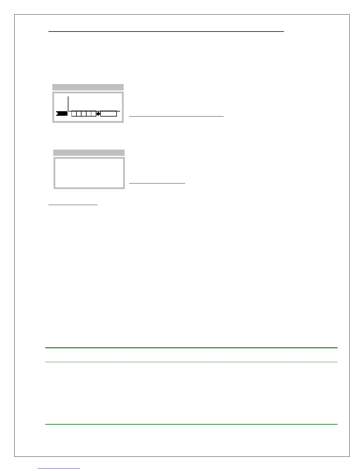
FAULT= 00000020
Sensor Removed
(See O&M Manual)
►Next
>Menu >F!
Fault Alarms
When a fault alarm occurs, the Main Display appears as shown below. By default, new alarms are
inhibited, and active alarms are held so that relays controlling lights, sirens, and fans may continue to
operate (this behavior may be modified on the Alarms Setup pages). Faults are permitted to clear
automatically, without operator intervention, if they do not persist.
Figure 49. Fault alarm (Main Display)
Selecting the fault alarm flag causes the transmitter to display the fault code on line 1, and a description
of the problem(s) on line 2. Selecting the Next function causes line 2 to display the next fault, if any.
Figure 50. Fault page
Corrective Actions
Transmitter faults may be caused by improper wiring, ground loops, power supply sizing, current loop
receivers, and other external factors.
1. At power on, transmitters can demand 2 or 3 times the normal amount of supply current. If the
supply is not sized properly, transmitters may not power on, or may produce a fault in the external
power supply. If this is suspected, try starting transmitters one at a time using switch SW5 on the
CPU Board.
2. Check that each transmitter has the proper supply voltage at TB1 on its Power Supply Board. The
D12 Toxic Gas Transmitter requires at least 12v in all wiring modes.
3. When troubleshooting, it is permissible to temporarily swap sensors, generators, and board stacks
with other transmitters. When finished, you MUST RE-VERIFY all transmitter settings, especially
sensor, alarm, and 4-20mA settings. Also note that swapping components may result in losing data
log records, since the log is dependent on sensor part numbers, and the full-scale range.
Table 10 lists transmitter faults and corrective actions.
Table 10. Fault descriptions
ADC0 Read Error
The analog-to-digital converter channel
assigned to the sensor’s gas concentration
output signal has failed, or is out of range.
1. Cycle power off and on
2. Replace sensor
3. Replace upper stack
4. Replace full stack
LCD Busy Error
The LCD driver chip cannot recover from an
internal error.
1. Cycle power off and on
2. Replace upper stack
3. Replace full stack
PPM
H2S
F!
Main Display