ATI Series D12 Toxic Gas Transmitter with H10 Smart Sensor
Revision N (7/15) 25
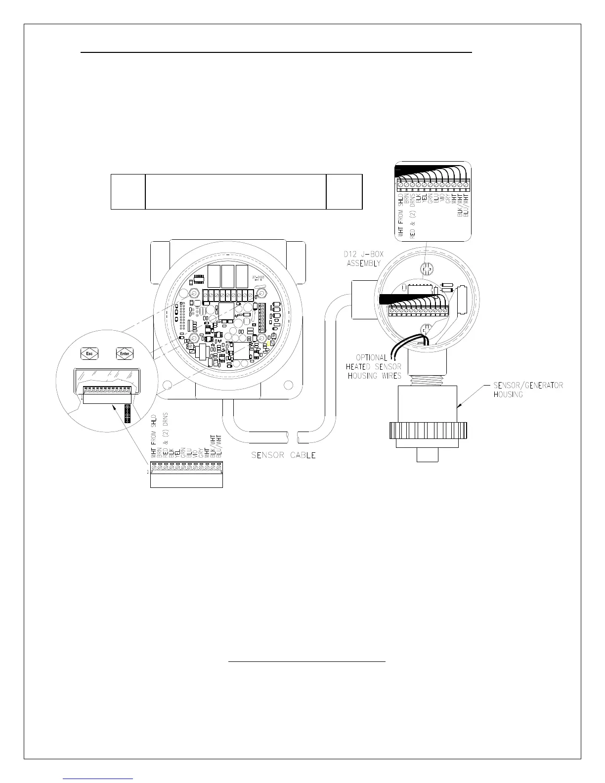
Remote Sensor Wiring
The figure below shows the wiring of the remote sensor option, which allows separation of the
transmitter and sensor by up to 50 feet. Interconnect cable is sold separately. Connections are made to
terminal blocks in the transmitter and J-box (junction box) assembly. The sensor/generator housing is
threaded into the J-box, and connected to a 14-position header. Do not allow exposed wires contact
each other, the printed circuit boards, or any components.
D12 GAS TRANSMITTER
NOTE: When Optional Heated Sensor housing is ordered, 2 Cond. Wire must be used to
Connect from Junction Box to Transmitter or External 24V power Source. ATI can
supply 2 Cond. 20 Awg wire our part # (31-0008) sold as /ft. if requested. If connected
as a 2-wire device an customer supplied 24V power source must be used to supply
voltage required to make heater circuit functional. A 3 or 4-wire device can be hooked
to the transmitter as shown in Fig 22 on page 27.
Figure 20 - Remote H10 Sensor Wiring
Recommendation: run cable
Through metal conduit.