ATI Series D12 Toxic Gas Transmitter with H10 Smart Sensor
Revision N (7/15) 22
The HART multi-drop connection permits up to 15 transmitters to communicate digitally on the same
bus, but at the cost of analog current signaling. Setting the transmitter’s polling address from 1 to 15
fixes the current loop output at 4mA. According to HART specifications, the current loop must be
terminated with a load resistor between 230 and 1100 ohms; however, transmitter specifications restrict
the maximum analog output resistance to a lower value (see Specifications). The term, “active source”,
refers to a transmitter that is not loop powered, and sources current from power applied to it on separate
terminals. Size the power supply according to the number of transmitters, the current demand of each
transmitter (see specifications), and wire resistance. Wire resistance must not be allowed to drop the
Primary Supply Voltage below 12V at the terminals of any transmitter. Hint: use at least 14 AWG wire
on supply connections (shown in bold).
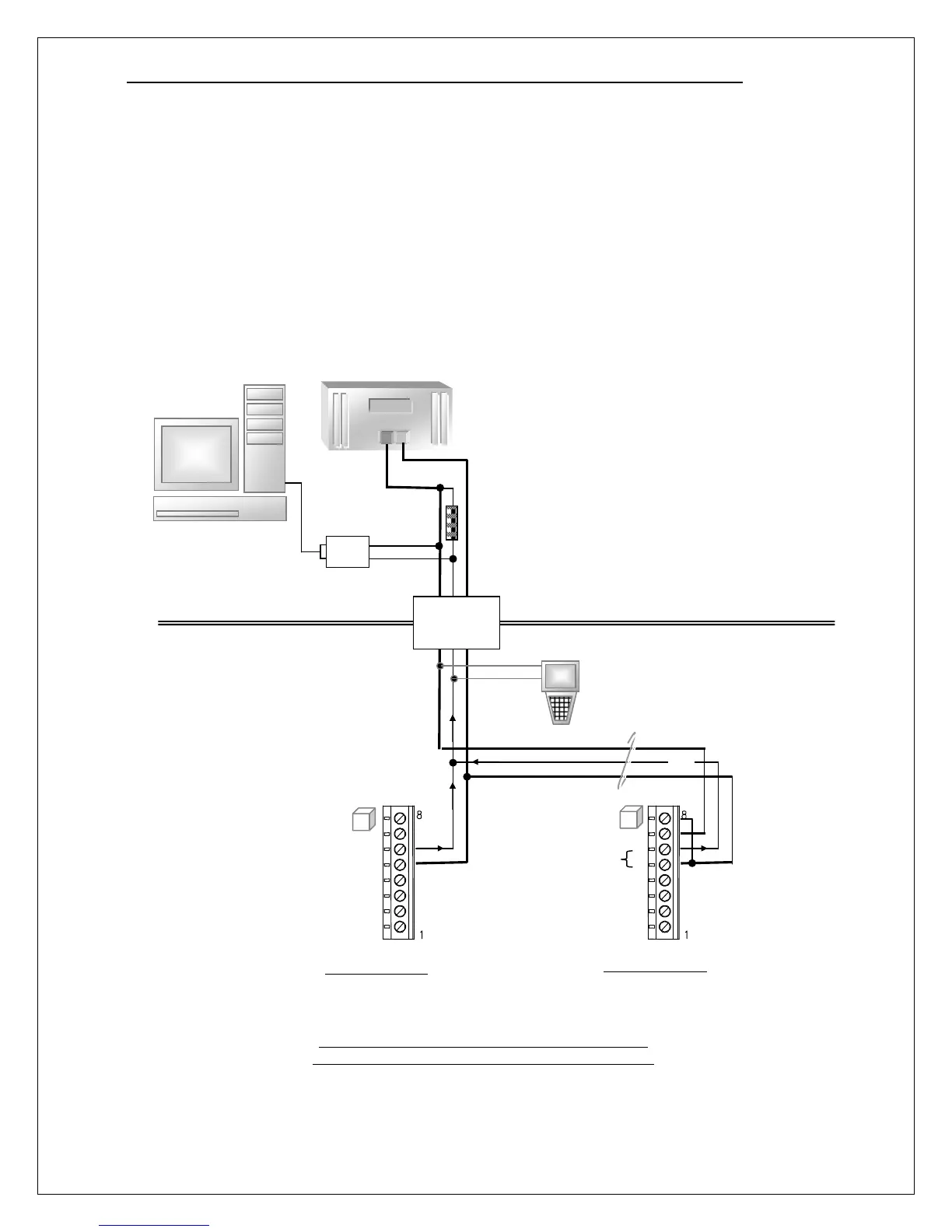
Figure 17. HART Transmitter Operation, Multi-drop
Loop Powered (2-Wire) and Active Source (3-Wire)
Modem
DCS or SCADA System
(primary master)
Load Resistor for
Digital Signaling Only
(Required)
Supply Voltage
(12v Minimum)
Hand-held Communicator
(secondary master)
Optional
Barrier/Isolator
for Hazardous
4mA
Primary Supply
12 to 30 VDC
Class @ Power
Source
4mA
N x 4mA
2-Wire Transmitter
(H10 Sensor Version, Only)
3-Wire Transmitter
(H10, Cat. Bead, and