ATI Series D12 Toxic Gas Transmitter with H10 Smart Sensor
Revision N (7/15) 41
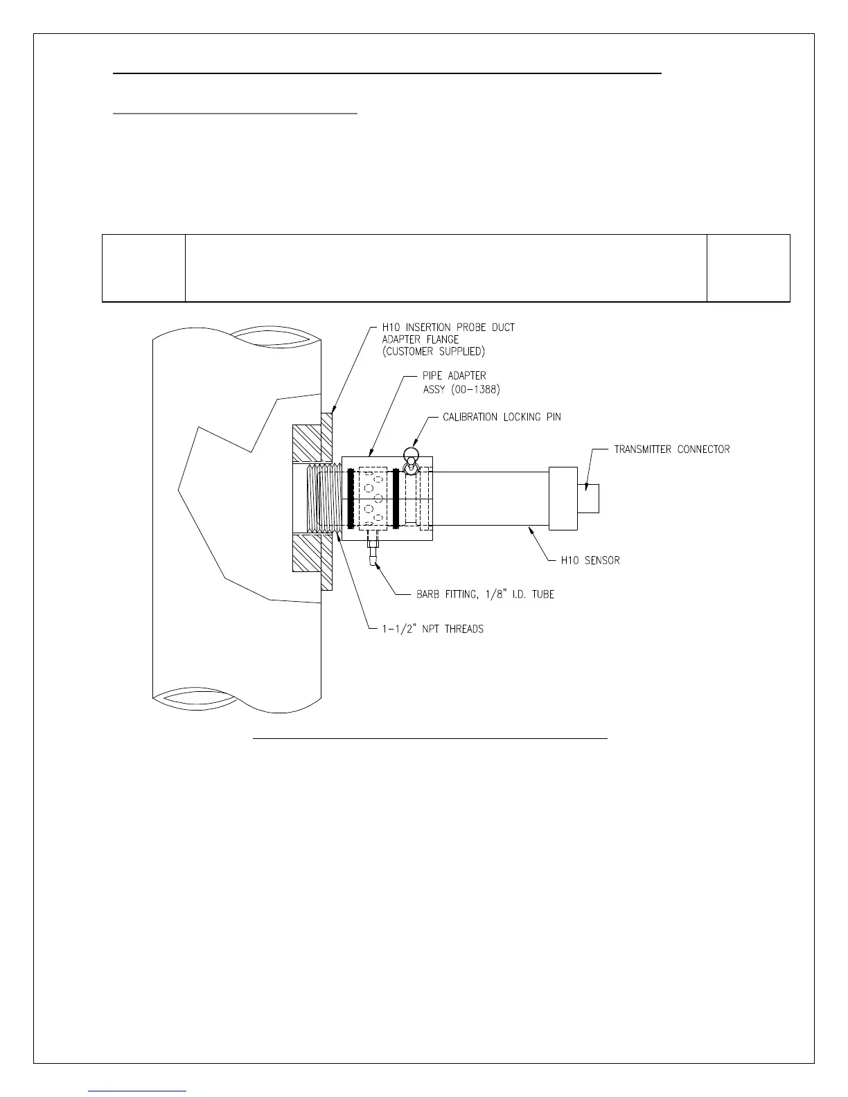
Calibration of Duct-Mount H10 Sensors
To Zero and Span calibrate a duct-mounted H10 sensor; pull the sensor out of the duct until the
calibration locking pin clicks into the retaining slot. By pulling back slowly, the retaining pin will drop
into place and automatically locate the sensor just behind the gas inlet port. Connect a length of tubing
from the gas regulator to the barb fitting, and then follow the zero and span calibration procedures
detailed earlier.
Figure 38. Calibration of duct-mount H10 sensors (ATI-0664)
For best results, pressure in the pipe
or duct should be neutral, or slightly
negative. Positive pressure may restrict the flow of calibration gas to the
sensor, resulting in an inaccurate calibration.