ATI Series D12 Toxic Gas Transmitter with H10 Smart Sensor
Revision N (7/15) 56
Alarm Relays
The D12 transmitter provides three optional SPDT mechanical relays rated for 5 amps, non-inductive
loads at 250VAC. These relays are suitable for switching small loads, such as horns and warning
lights, but should not be used to switch motors or other high current, inductive loads.
Each relay is assigned to one of the four alarms, and may be programmed as normally energized
(failsafe), or normally de-energized. A normally energized relay will have electrical continuity between
its C and NO contacts (while the transmitter is powered on), and will be open between its C and NC
contacts. Conversely, a normally de-energized relay will have continuity between its C and NC
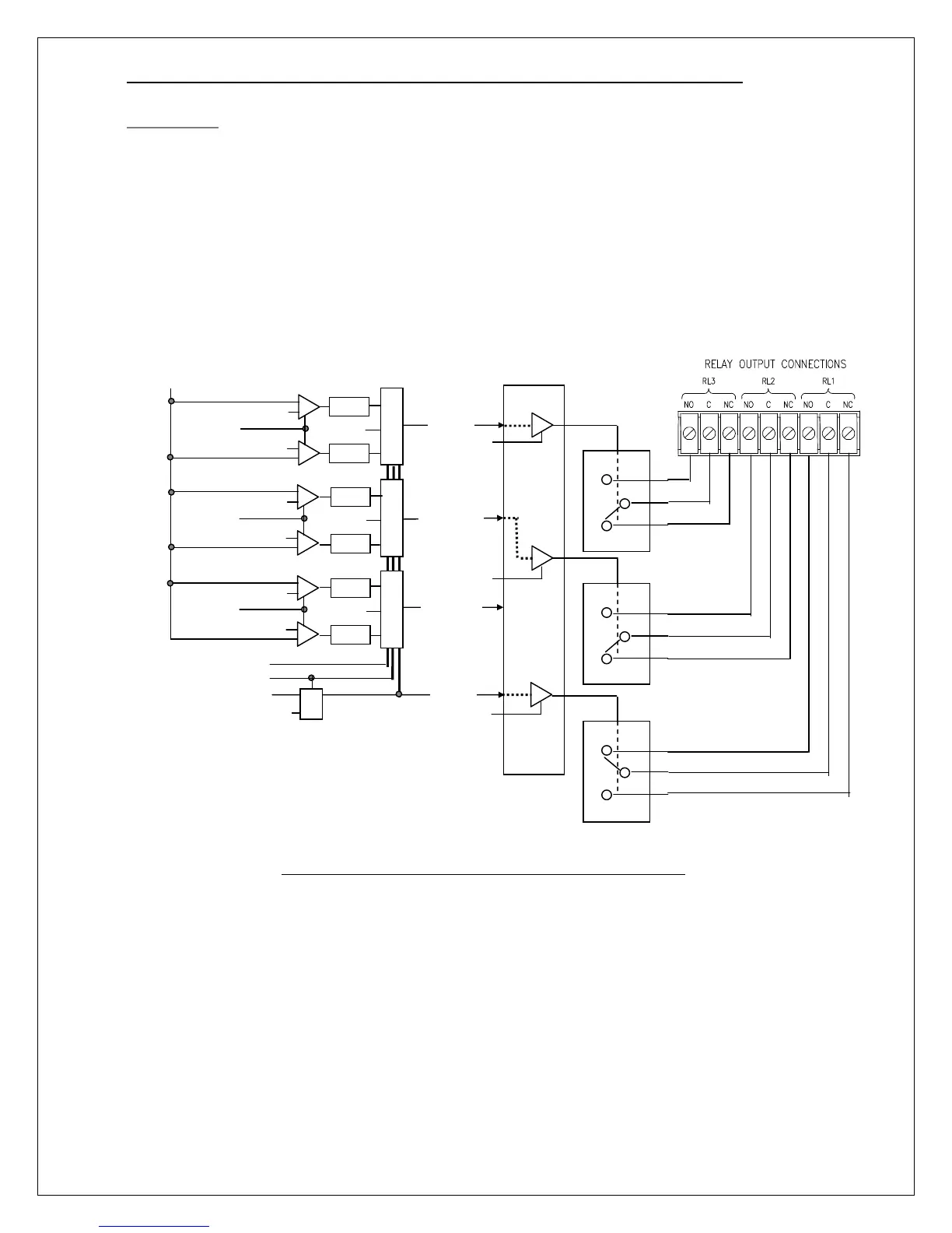
contacts, and will be open between its C and NO contacts. Figure 51 illustrates the function of alarm
and relay variables on the operation of the relays.
Figure 51 Alarm relay schematic(default – no alarms active)
Res_Point
A
Gas
Relay Logic
(- - - user configurable)
Alarm
RL2 Failsafe
S
R
S
R
S
R
Rdly
W
Sdly
W
Rdly
A
Sdly
A
Rdly
C
Sdly
C
Inhibit
A
Set_Point
Res_Point
W
Set_Point
Res_Point
C
C
Set_Point
C