ATI Series D12 Toxic Gas Transmitter with H10 Smart Sensor
Revision N (7/15) 35
Sensor More Page
Figure 31. Sensor “more” page
Table 5. Sensor “more” variables
Cal_History
Cal_History is a link to the Calibration History page (see Sensor Calibration
Records).
Test_History
Test_History is a link to the Auto-test History page (see Auto-test History)
Temp
The Temp variable is the sensor temperature reading in degrees Celsius,
which may be adjusted up or down to achieve a temperature offset calibration.
Changing H10 Sensors and C18 Generators
H10 sensors and C18 generators may be “hot-swapped”, that is, removed and replaced with power
applied. To remove, rotate the sensor housing lock-ring ¼ turn clockwise (bottom view), slide the
molded carrier down, and carefully pull down on the sensor and/or generator body. To install, reload
the carrier, push it into the housing, and rotate the ring ¼ turn counter-clockwise (bottom view).
Removing Sensors
Removing the sensor with powered applied starts a 60 second count down timer, during which alarms
are inhibited, and the current loop output is fixed at 4.0mA (17.4mA for Oxygen sensors). This
“immunity” period should be long enough to reinstall the sensor, or install a replacement sensor. If
more time is needed, the count may be stopped indefinitely by selecting “Hold”, which causes it to
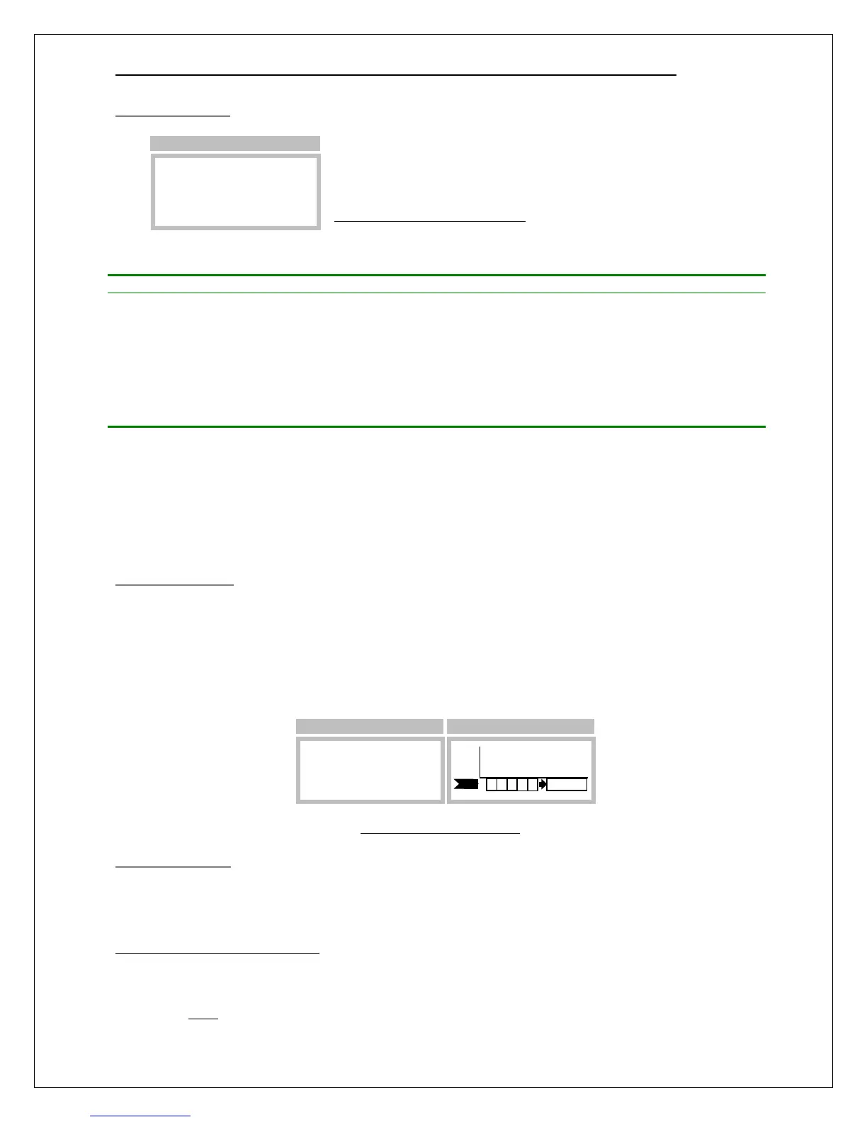
blink. A “Sensor Removed” fault will occur if a sensor is not installed before the timer expires. Figure
32 illustrates the display sequence associated with removing the sensor.
Figure 32. Sensor removal
Installing Sensors
The transmitter maintains a copy of the previously installed sensor and compares the part numbers of
the new sensor with the old. If the part numbers match, the transmitter sequences the startup review as
normal, beginning with the sensor information
3
. If they do not match, review halts and waits for the
3
As a convenience during field replacement, the transmitter sets the new sensor’s full-scale range, blanking, damping, and
alarms to match the previously installed sensor. This could cause confusion when transferring sensors from field transmitters
to shop transmitters for calibration. During review, the shop transmitter will display the settings of the previously installed
sensor, which might not match the field transmitter. Fortunately, this is not a real problem. The sensor may be calibrated as
►Cal_History
Test_History
Temp= 21.7°C
>Menu >Setup >Sensor >More
PPM
H2S
Main Display
Sensor Removed
Sensor Removed