ATI Series D12 Toxic Gas Transmitter with H10 Smart Sensor
Revision N (7/15) 28
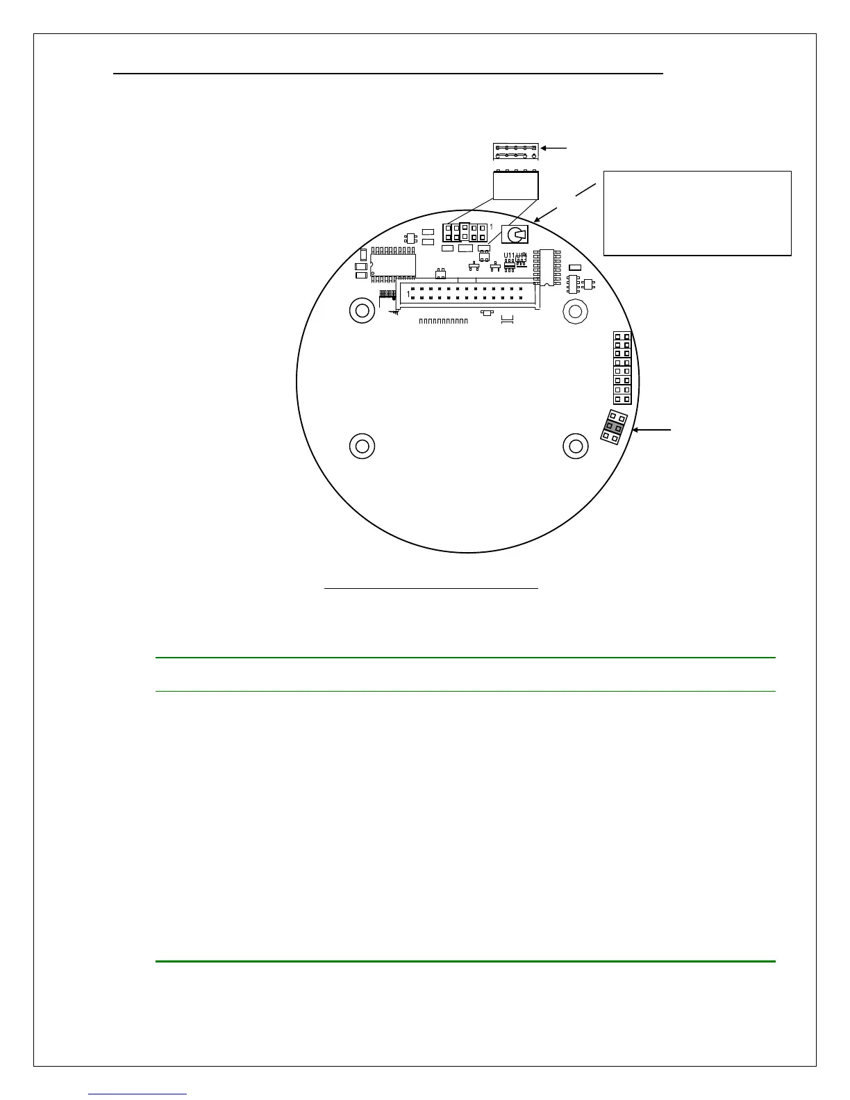
CPU Board Configuration
Install one jumper plug on
JP4 as prescribed by
communication interface.
If equipped with relays,
install the relay option
jumper on pins 3-4 of JP1.
Set switch SW5 to ON
before replacing the
housing cov
Figure 23. CPU Board configuration
Table 3. Communication option jumpers
Label
HART Bell 202 N/A
No plug required (okay to install any)
Modbus RS232 “RS232” Use to connect one transmitter to a master device in a
“point-to-point” configuration. See “D12 Modbus Manual”
for details.
Modbus RS485 “RS485” Use to connect up to 4 transmitters to a master device in a
“multi-drop” configuration. Each transmitter connection
biases and terminates the transmission line, as shown
below. See “D12 Modbus Manual” for details.
Modbus RS485 “RS485
Unterminated”
Use to connect more than 4 transmitters to a master
device in a “multi-drop” configuration. Transmitters are
connected without adding bias or termination. Install one
(terminating) “RS485” jumper plug on transmitter at
furthest end of transmission line. See “D12 Modbus
Manual” for details.
ASCII RS232 “RS232” Use to connect one transmitter to a printer, or system
terminal (see Data logging section).
After re-installing the
transmitter board stack, set
switch SW5 to ON before
replacing housing cover.
Jumper block on JP4
(see table above) Note
Install jumper on pins 3-4
of JP1 to enable relay
operation.
On