ATI Series D12 Toxic Gas Transmitter with H10 Smart Sensor
Revision N (7/15) 9
INSTALLATION
MECHANICAL MOUNTING
Transmitter
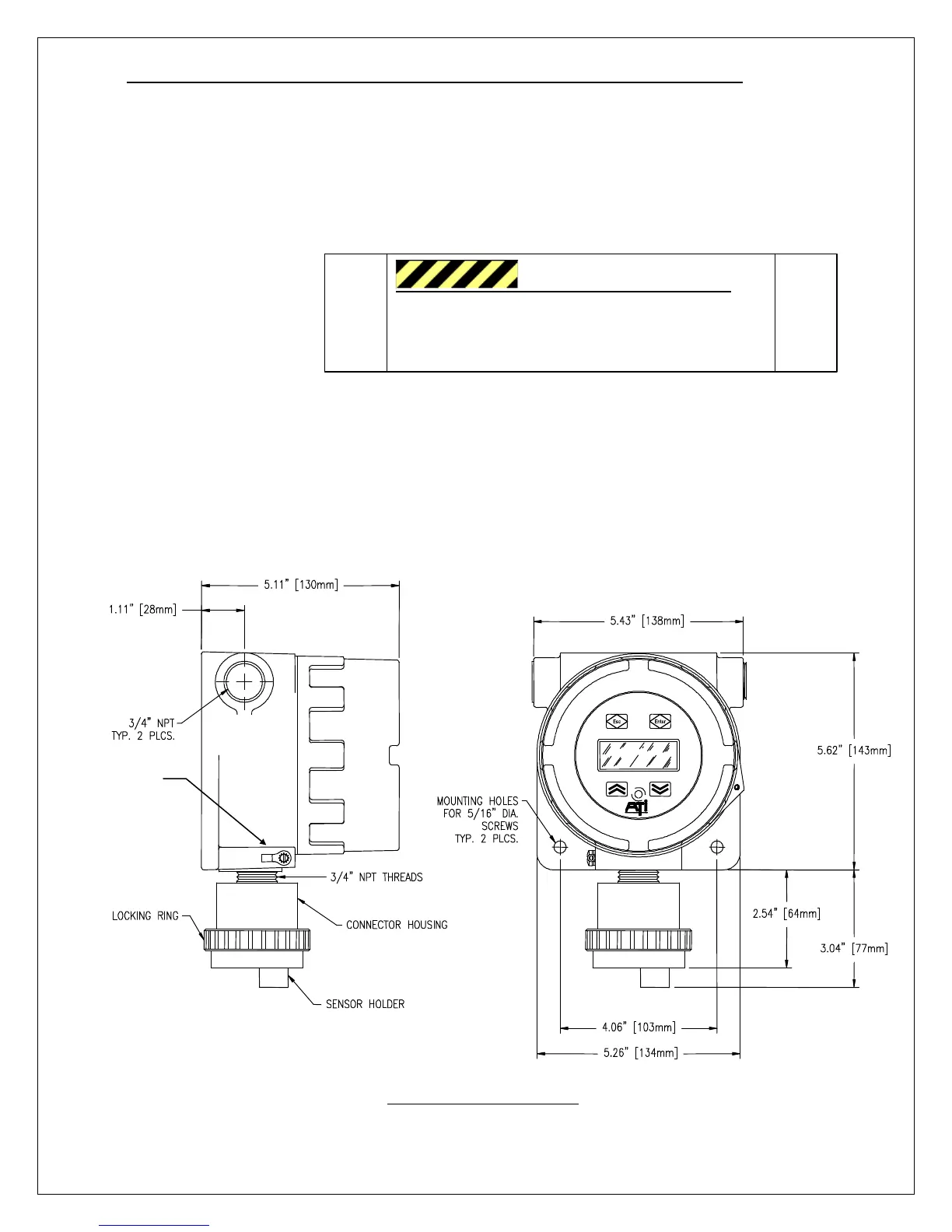
Figure 2 shows the
dimensions of the
transmitter enclosure and
the location and size of
the electrical conduit
connection. In locations
classified as hazardous,
the transmitter housing must be earth grounded, and an explosion-proof seal must be installed as
required by the local electrical code. The conduit or cable gland entry into the enclosure must be
sealed. If conduit is used, it must also be sealed internally at the housing entry. This is required to
prevent condensation from draining into the enclosure.
Seal conduit inside and out to keep out water.
Follow national, state, and local, electrical codes.
Secure the transmitter to a wall or flat surface through two mounting holes in the enclosure, as shown in
Figure 2. If appropriate fasteners are used, the transmitter may be supported by conduit alone.
Figure 2. Overall dimensions
D12 GAS TRANSMITTER
Housing Ground
HAZARDOUS LOCATIONS
Connect housing to earth ground. Use explosion
proof conduit, and seal it inside and out.
Follow national, state, and local, electrical codes.