ATI Series D12 Toxic Gas Transmitter with H10 Smart Sensor
Revision N (7/15) 19
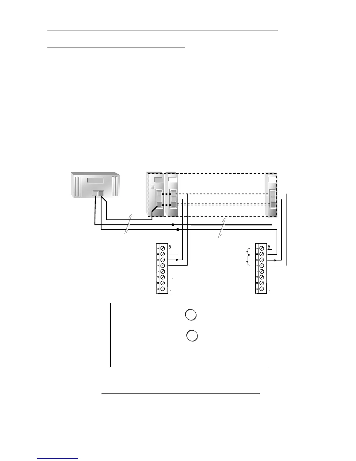
Current Loop Receiver, Dual Supplies (4-Wire Mode)
To reduce the power requirement of a single current loop supply, the transmitter may be powered from
both a primary and loop supply, providing the following conditions are met.
1. Supply grounds are directly connected to minimize ground loops, and,
2. The Primary Supply Voltage is at least 12V, and must be equal to, or exceed, the Loop Supply
Voltage, as measured at instrument terminals.
Size each power supply according to the number of transmitters, the current demand of each (see
specifications), and the wire resistance. The wire resistance must not be allowed to drop the Primary
Supply Voltage below the Loop Supply Voltage, which must be at least 12V, as measured at the
terminals of any transmitter. Hint: select a Primary Supply with a higher voltage output than the Loop
Supply, and use 12-14 AWG wire, if possible. Keep the number of transmitters supplied by the
Primary Supply low, and verify the voltages at the terminals of the transmitter furthest from the Primary
Supply.
Figure 14. Current Loop Receiver, Dual Supplies (4-Wire Mode)
Primary Supply Voltage
must not drop below Loop
Supply Voltage at terminals
of any transmitter.
Primary supply connections
to minimize voltage drops.
Connect supply commons to
minimize ground loops and
voltage drops that might
reduce the Primary Supply
Voltage below the Loop
Supply Voltage, at transmitter.
Select a Primary Supply with a
higher voltage output, and,
1
2
(Vprimary >= Vloop>=12V )
Sig
Sig
Multichannel Current Loop Receiver with Integral 24V Supply
(Channels are typically not isolated from supply)
Primary Supply
24 to 30 VDC
Class 2 Power
Source