ATI Series D12 Toxic Gas Transmitter with H10 Smart Sensor
Revision N (7/15) 57
Relays Setup
Relays are configured in the Relays Setup page, which is accessed by selecting Menu, Setup, Alarms,
and (Relays) Setup. Select the alarm trigger source (Alarm,Warning,Caution,Fault), and failsafe
property (Normal-On or Normal-Off).
Figure 52. Relay setup page (example)
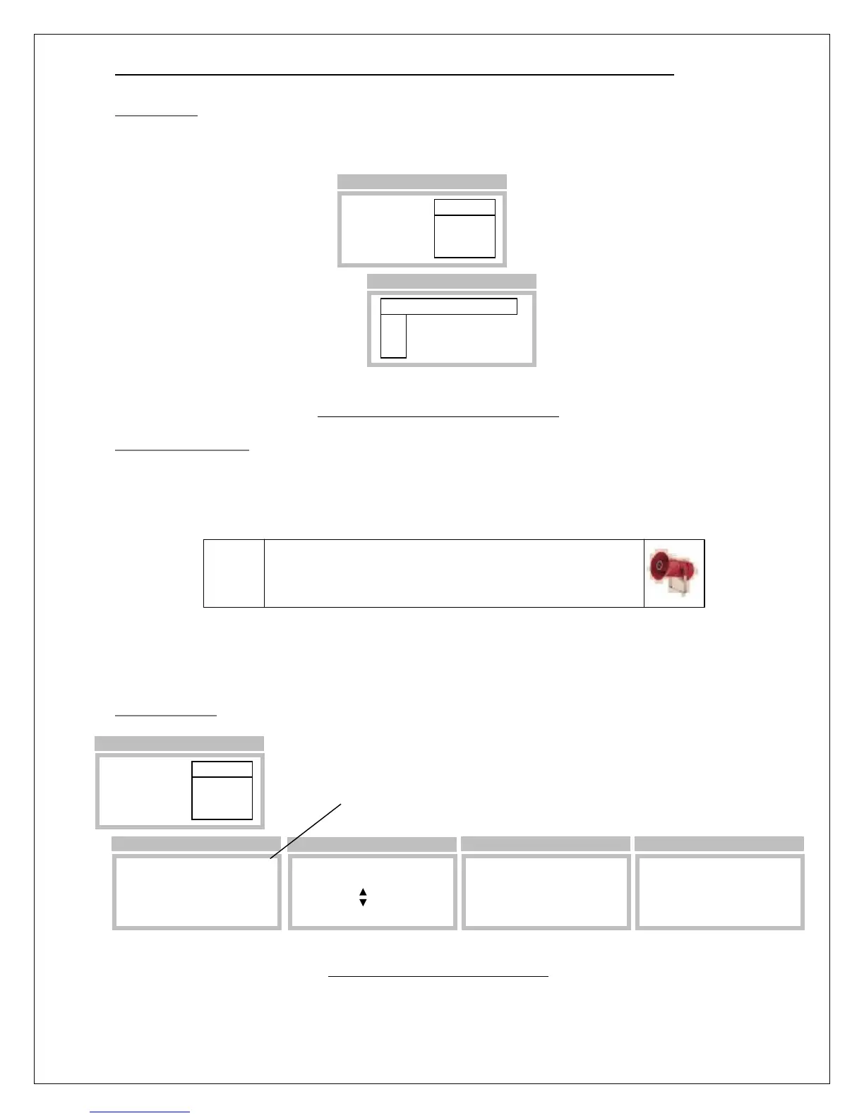
Testing Alarm Relays
Relays are tested by triggering (simulating) their assigned alarms on the Relay Test page. To trigger an
alarm, scroll the “Select” variable up and down until an X appears below the letter representing the
alarm. Save the selection by touching the Enter key, and move the cursor to the function labeled
“Start”.
When ready, select “Start” to begin the test. “Start” will be replaced by, “Any key to Stop”, and
touching any key will end the test.
Relay Test Page
Figure 53. Relay test page example
Alarm Relays
Warning ►Setup
Caution Test
Inhibit
>Menu >Setup >Alarms
Rly Alarm Normal
RL1►Fault On
RL2 Warning Off
RL3 Alarm Off
>Setup
Caution: devices wired to the relays may activate
when “Start” is selected. Be sure to inform proper
personnel before performing the test.
Alarm Relays
Warning Setup
Caution ►Test
Inhibit
>Menu >Setup >Alarms
Warning: this wi
C W A F
►Select _ _ _ _
Start
>Test
Warning: this wi
C W A F
Select _ X X _
Start
>Test
Warning: this wi
C W A F
Select _ X X _
>Start
>Test
Warning: this will activate transmitter alarm relays for a maximum
of 5 minutes. Notify proper authorities prior to performing this test.
Warning: this wi
C W A F
Select _ X X _
Any key to STOP
>Test