Hardware Installation Manual 16 Document #: LTRT-28030
3.2.1 LED Descriptions
This section describes the LEDs on the front panel of the chassis.
3.2.1.1 SYS LED
The SYS LED indicates the device's operating status, as described in the table below.
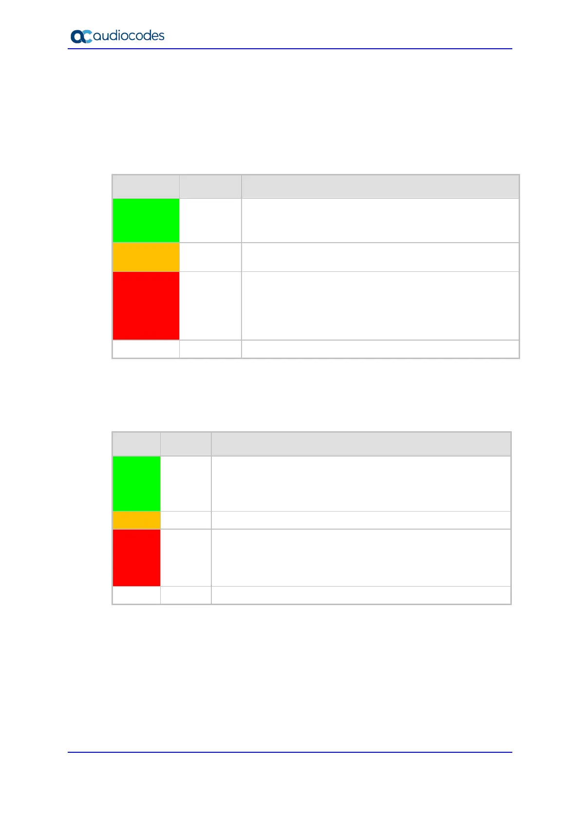
Table 3-3: SYS LED Description
Color State Description
Green
On LED lit as a result of one of the following:
Device is operating normally
During first stage of boot up when device is powered on
Orange
On Chassis is approaching high temperature threshold, but not
yet critical
Red
On LED lit as a result of one of the following:
Fault detected in CPU module
Incompatible or faulty software version (.cmp file)
detected during boot up
Approaching critical high temperature threshold
Off No power
3.2.1.2 TEL LED
The TEL LED indicates the status of the FXS blades, as described in the table below.
Table 3-4: TEL LED Description
Color State Description
Green
On LED lit as a result of one of the following:
During booting up phase
During normal operation, indicating normal FXS blade
operation
Orange
At least one DSP has reached the high temperature threshold
Red
On LED lit as a result of one of the following:
During initial phase of power-up
Failure detected in at least one FXS blade
No FXS blades detected in the chassis
- Off No power.

 Loading...