MediaPack Analog Gateways 31 MP-1288
Hardware Installation Manual 5. Cabling the Device
5.2 Connecting Ethernet Interfaces
The device provides two 100/1000Base-T Gigabit Ethernet ports (RJ-45) for connecting to
the IP network (e.g., LAN). The ports support half- and full-duplex modes, auto-negotiation,
and straight or crossover cable detection.
The ports can operate as a pair (Ethernet Group) to provide 1+1 port redundancy, where
one port serves as the active port while the other as standby. When the active port fails,
the device switches to the standby port.
The cabling specifications and procedure for connecting the device to the LAN is as
follows:
Cable: Straight-through, Category (Cat) 5, 5e or 6 cable
Connector: Standard RJ-45
Connector Pinouts:
Table 5-1: RJ-45 Connector Pinouts for Ethernet Ports
Pin Signal Name
1
Ethernet signal pair
2
3
Ethernet signal pair
6
4
Ethernet signal pair
5
7
Ethernet signal pair
8
Shield
Chassis ground
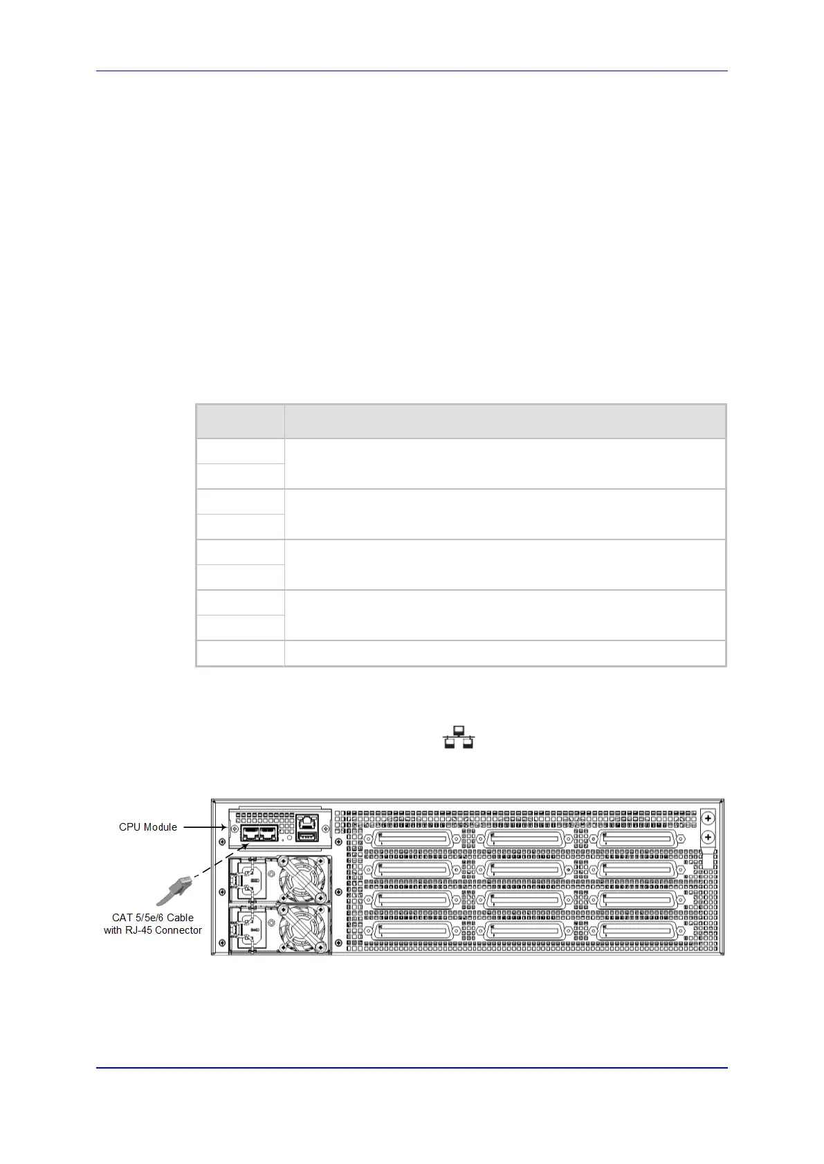
To connect the Ethernet interfaces:
1. Connect the RJ-45 connector, at one end of a straight-through Cat 5e or Cat 6 cable,
to one of the Ethernet ports (labeled ) on the CPU module located on the
chassis' rear panel, as shown below:
Figure 5-5: Connecting the LAN Ports
2. Connect the other end of the cable to your network.
3. For 1+1 Ethernet port redundancy, repeat steps 1 through 2 for the standby port.
Make sure that you connect each port to a different network (but in the same subnet).

 Loading...