Hardware Installation Manual 22 Document #: LTRT-28030
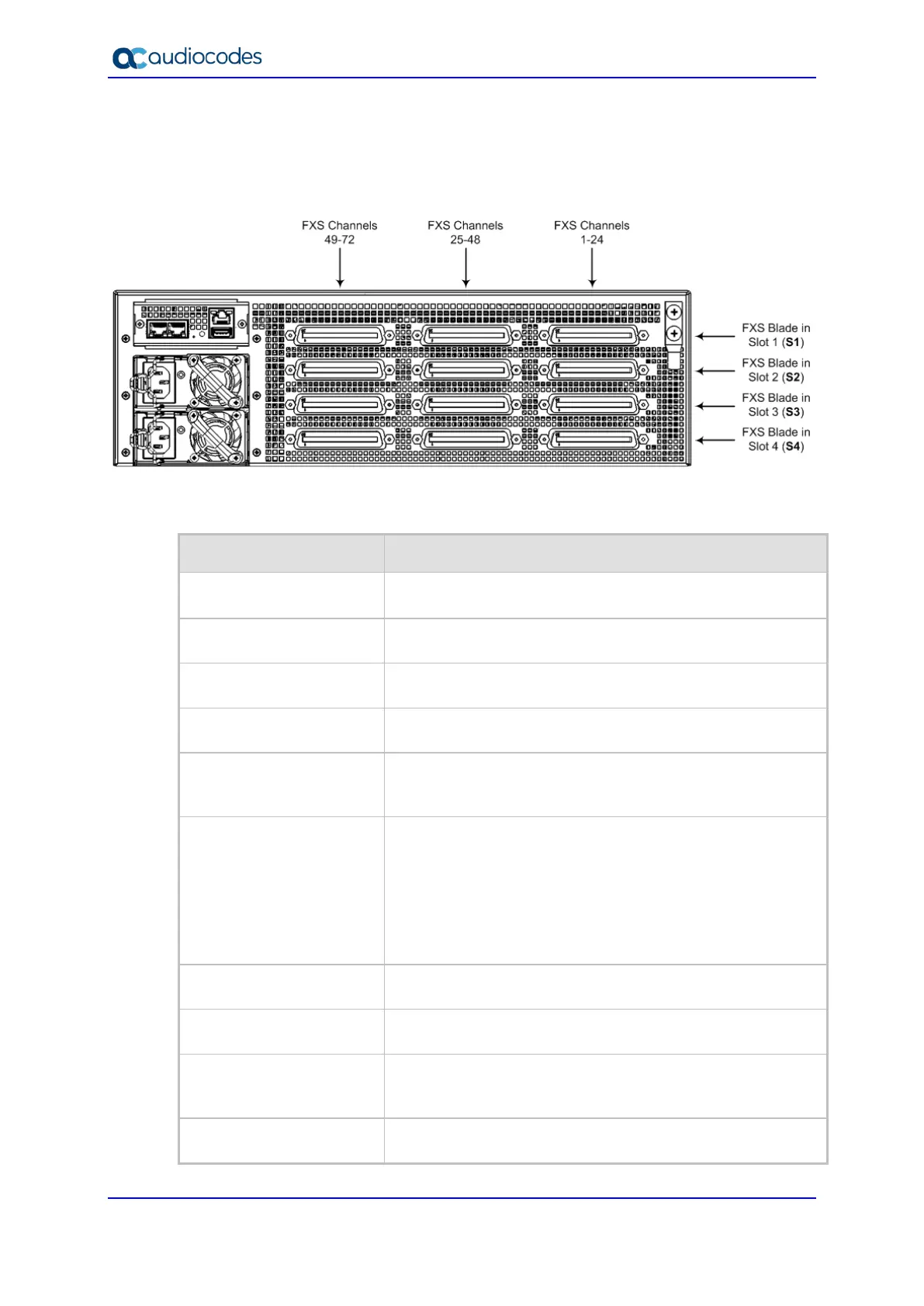
The FXS channel (port) number range of each FXS connector on an FXS blade is indicated
by the labels (FXS 1-24, FXS 25-48, and FXS 49-72) located on the rear panel above the
FXS blades, as shown below:
Figure 3-8: FXS Blades and FXS Channels per FXS Connector (Rear Panel)
The table below lists the specifications of the device's FXS ports.
Table 3-9: FXS Port Specifications
Specification Description
Analog Lifeline (PSTN
Fallback)
The FXS blade supports analog lifeline (PSTN Fallback). For
more information, see Section 5.4 on page 41.
Interface Type FXS connection via 50-pin CHAMP connector
FXS Signaling Formats In-band signaling DTMF (TIA 464B)
FXS Loop Impedance Up to 1500 ohm (including phone impedance)
Off-hook Loop Current
25 mA (maximum) on all ports
35 mA (maximum) on six ports per FXS Blade (for
emergency / elevator phones)
Ring Voltage (Sine)
54 Vrms
80 Vrms on six ports per FXS Blade (for emergency /
elevator phones)
Note:
Balanced ringing only.
Simultaneous ringing of 288 phones (72 per FXS Blade
given REN 3 load)
Ring Frequency 25-100 Hz
Maximum Ringer Load Ringer Equivalency Number (REN) 3
Caller ID Bellcore GR-30-CORE Type 1 using Bell 202 FSK
modulation, ETSI Type 1, NTT, Denmark, India, Brazil,
British and DTMF ETSI CID (ETS 300-659-1)
Polarity Reversal / Wink Immediate or smooth to prevent erroneous ringing

 Loading...