2 Specifications
© Copyright Reserved Autonics Co., Ltd. 25
2 Specifications
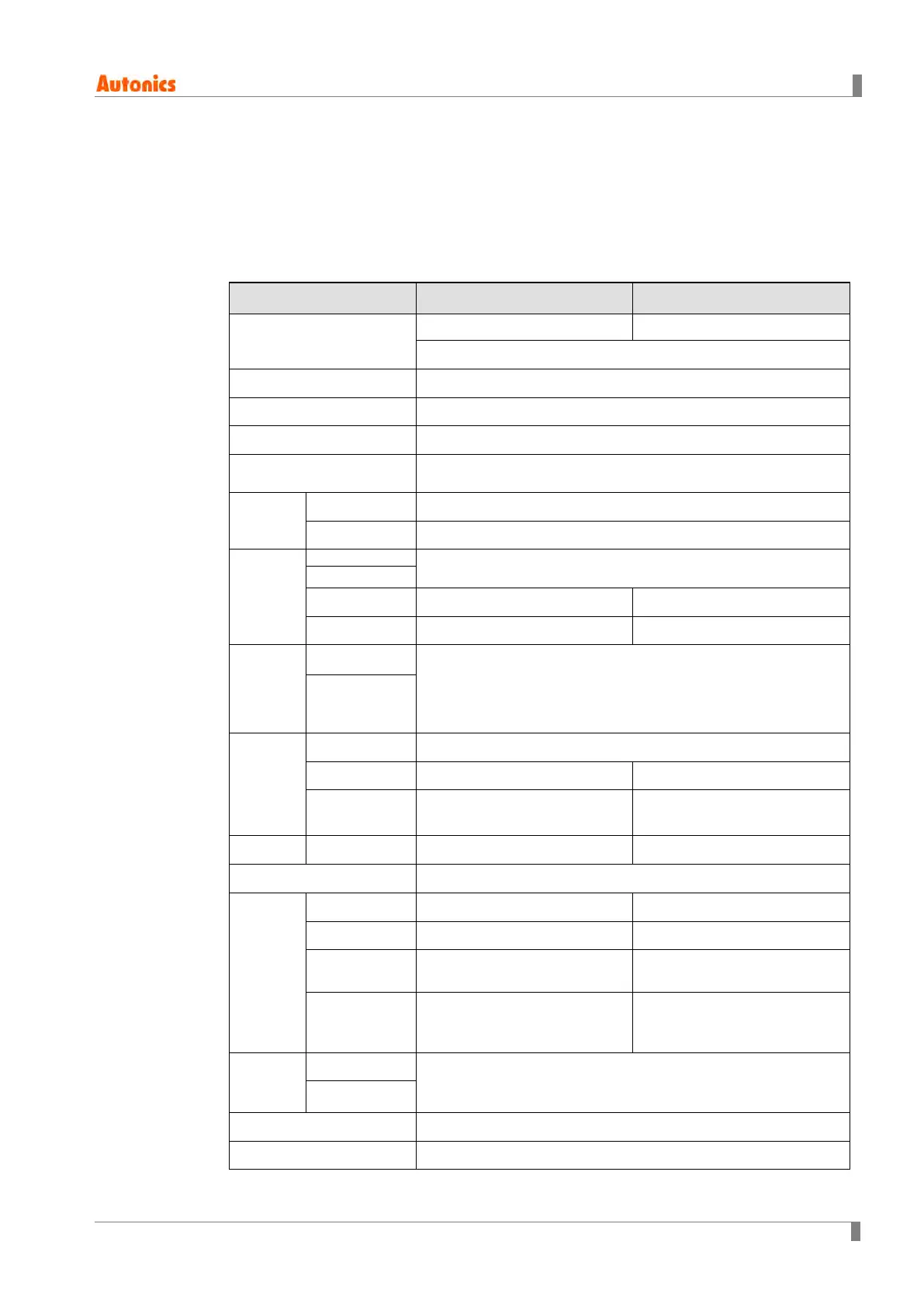
2.1 Ratings
Category TM2 Series TM4 Series
Number of Channels
2 channels 4 channels
Each channel insulated – Dielectric strength 1,000VAC
Power Supply
24VDC
Allowable voltage range
90% ~ 110% of rated voltage
Power Consumption
5W max. (At maximum load)
Indicating type
Non indicating type - Parameter setting and monitoring with externally
device (PC or PLC).
Input
type
RTD
DPt100 Ω, JPt100 Ω 3 wire (allowable line resistance: Max. 5Ω)
Thermocouples
K, J, E, T, L, N, U, R, S, B, C, G, and PLII (13types)
Indicating
accuracy
RTD
(Bigger one either PV±0.5% or ±1℃)±1 Digit Max.
Thermocouple
※
1
C·T Input
(±5% F.S.) ±1 Digit Max
-
Current output
(±1.5% F.S.) ±1 Digit Max
-
Influence
of
Temperatu
re
※
2
RTD
(Bigger one either PV±0.5% or ±2℃)±1 Digit Max.(In case of
thermocouple input, it is ±5℃ at -100℃ below)
Themocouples L ,U, C, G, R, S, B: (Bigger one either PV±0.5% or ±5℃)±1
Digit Max.
Thermocouples
Control
Output
Relay
250VAC 3 A 1a
SSR
12VDC ±3V 30mA Max. 22VDC ±3V 30mA Max.
Current
DC4-20mA or DC0-20mA
(Load 500ΩMax.)
-
Relay
250VAC 3A 1a
Communications output
RS485 communications output (Modbus RTU method)
Event
Input
Leakage current
Approx. Max. 4mA -
Contact
ON: Max. 1KΩ, OFF: Min. 100KΩ. -
Non-contact
ON: Max. 1.5V residual voltage
OFF: Max. 0.1mA leakage current
-
C·T
0.0-50.0A (Primary current
measurement range)
※C·T ratio (1000:1)
-
Control
type
Heating, Cooling
ON/OFF control, P, PI, PD, PID control
Heating &
Cooling
Hysteresis
RTD/ Thermocouples: 1~100℃/℉(0.1~100.0℃/℉) variable
Proportional Band (P)
0.1 ~ 999.9℃
 Loading...