6 Parameter Settings and Functions
88 © Copyright Reserved Autonics Co., Ltd.
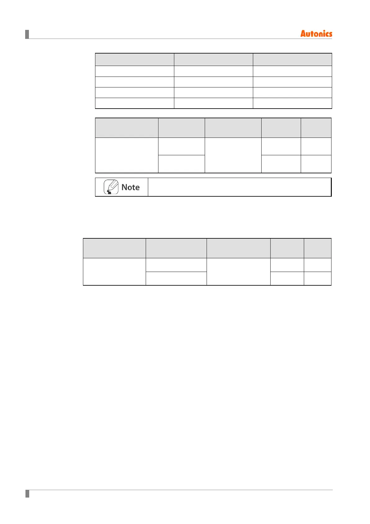
DI-1 DI-2 Multi SV No.
OFF OFF SV-0
ON OFF SV-1
OFF ON SV-2
ON ON SV-3
Group Parameter Range
Factory
Default
Unit
Option Setting Group
(Digital Input Setting)
Digital Input 1
Function
OFF, STOP, AL-
RESET
Manual, Multi-SV
STOP -
Digital Input 2
Function
AL-RESET -
Multi SV parameter will be activated only if Multi SV is more than 2.
6.6.4.2 Digital Input Terminal Target Channel
Users can set a target channel to which digital input terminal function will be applied.
Group Parameter Range
Factory
Default
Unit
Option Setting Group
(Digital Input Setting)
Digital Input1_Ch
CH1, CH2
CH1 -
Digital Input2_Ch CH2 -
6.6.5 Error Detection
The controller diagnoses input signals for errors and displays messages accordingly.
These messages inform the user of device problems.
The following conditions may result in errors. When an error occurs, the display LED
at the front flashes at 0.5 second intervals.
The sensor input is higher than operational temperature range.
The sensor input is lower than operational temperature range.
Input sensor is disconnected or not connected.
Once the cause of the error is solved (sensor connected/return to display range), the
error status is released and the device continues to run normally.
 Loading...