4 Connections and block diagram
© Copyright Reserved Autonics Co., Ltd. 35
Shaded terminals are available only for TM4-N2□B
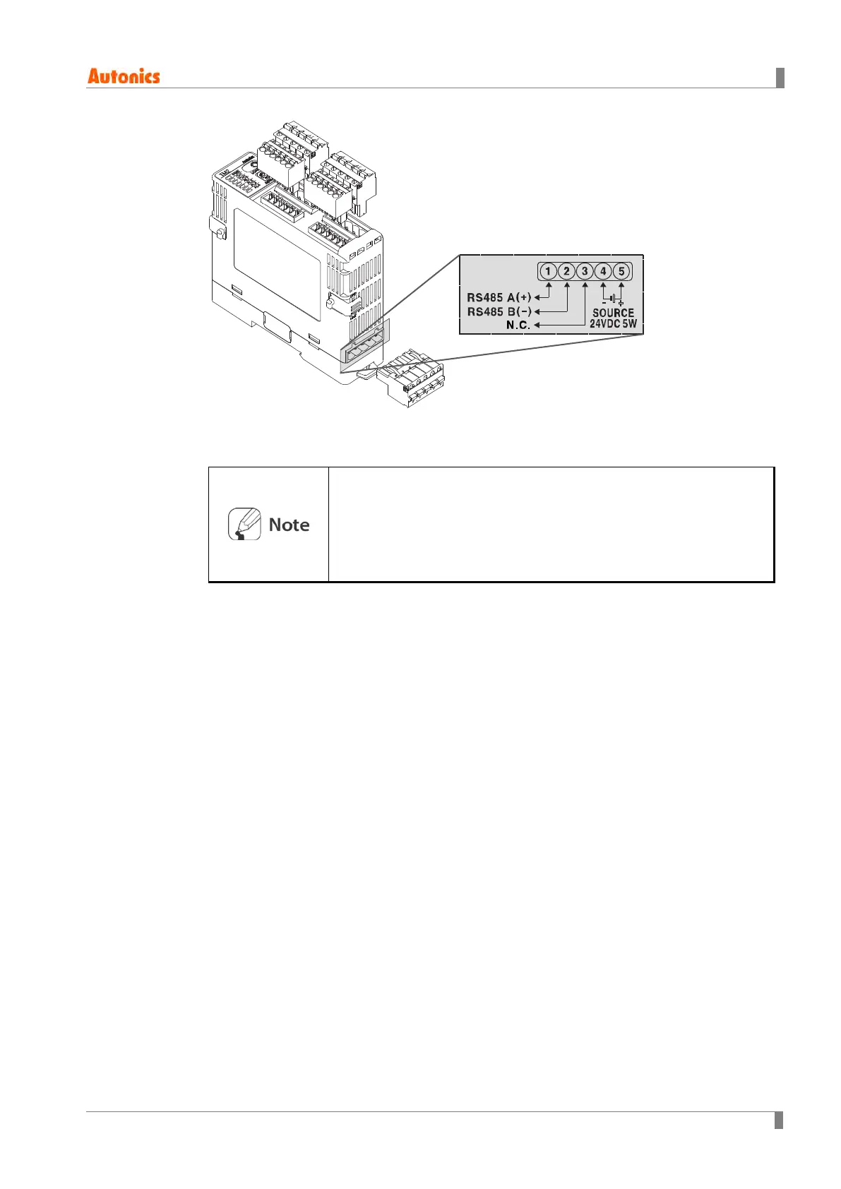
Pay attention to the connection direction when wiring the power
supply/communications connection terminal.
It is recommended to use lines with AWG 28 to 16 when connecting
the sensor or compensation wire.
It is recommended to use lines thicker than AWG 24 for SSR output.
It is recommended to use lines thicker than AWG 20 for relay output.
4.2 Wiring Precautions
Mixing up the input terminals with output terminals and vice versa can lead to product
damage.
Use only sensors supported by the product.
Make sure to connect rated SSRs or loads to the output terminals.
Make sure to connect the communication cable with correct communication terminals
(A, B).
Make sure to observe correct polarity of power source terminals. (+ and -).
4.2.1 Sensor Connection
4.2.1.1 Compensation Wire Connection
For thermocouple sensors, use compenstion wire of the same specification as input
sensors. Using an extension wire of different specification and/or material will increase
 Loading...