4 Connections and block diagram
36 © Copyright Reserved Autonics Co., Ltd.
inaccuracy of temperature sensing. It is recommended to choose high performance
compensation wire for more reliable sensing.
4.2.1.2 Measurement Error
Do not mix up the direction of the input sensor connector.
Carefully adjust both load and sensor positions.
Make sure the sensor is securely attached to the input connector.
4.2.1.3 Wiring with AC Power Lines
Do not put the sensor lines in close proximity of the AC power lines.
.
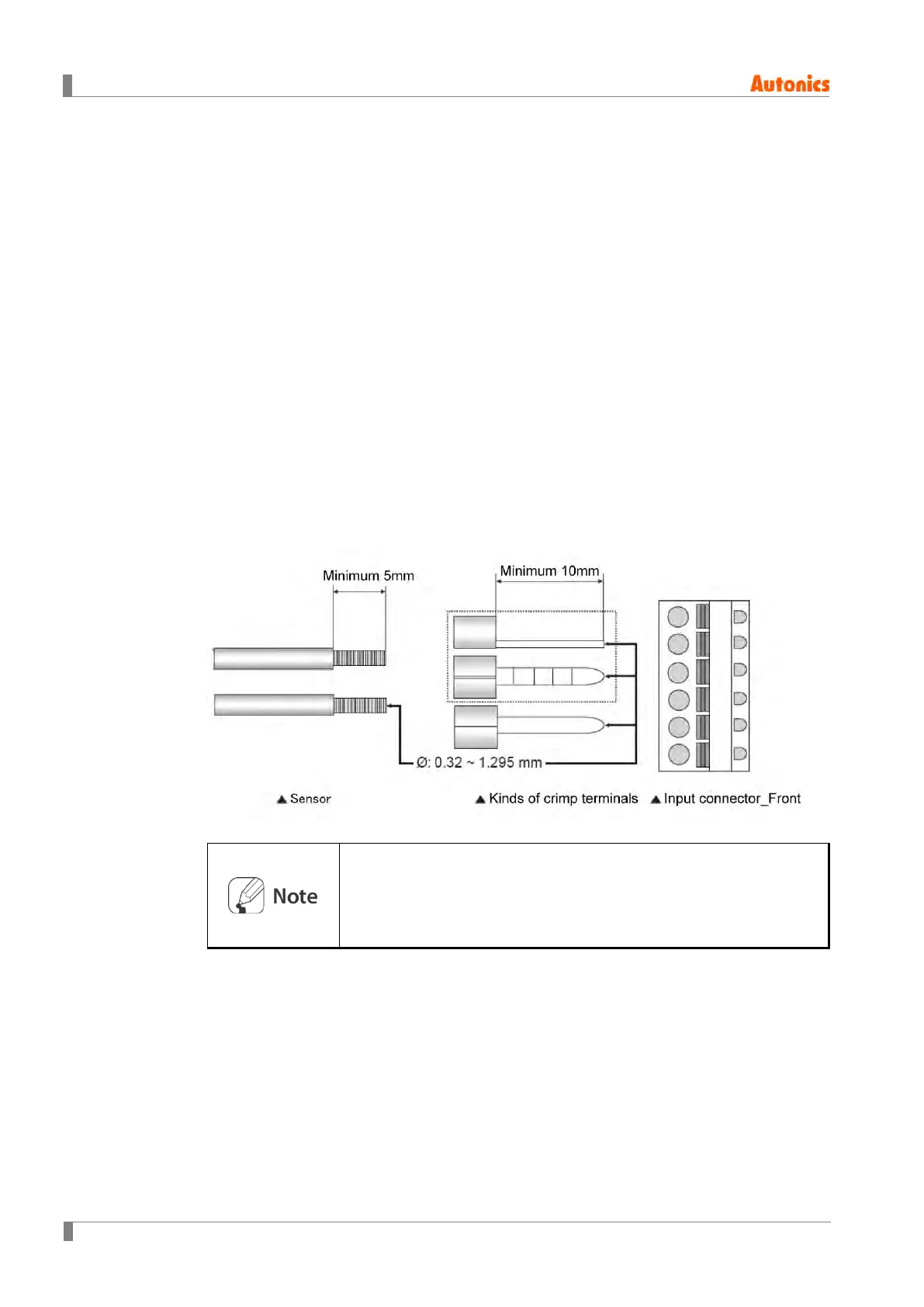
4.2.1.4 Input Sensor (or compensating lead wires) Connection
Make sure the sensor is completely inserted in the connector using a
crimped terminal.
The sensor and crimp terminal to attach at the input connector must
be AWG 28 to 16 (Ø: 0.32 to 1.295 mm).
Fix the sensor to the connecter properly for accurate measurement.
 Loading...