Connecting a BUPS
Issue 2 July 2005 57
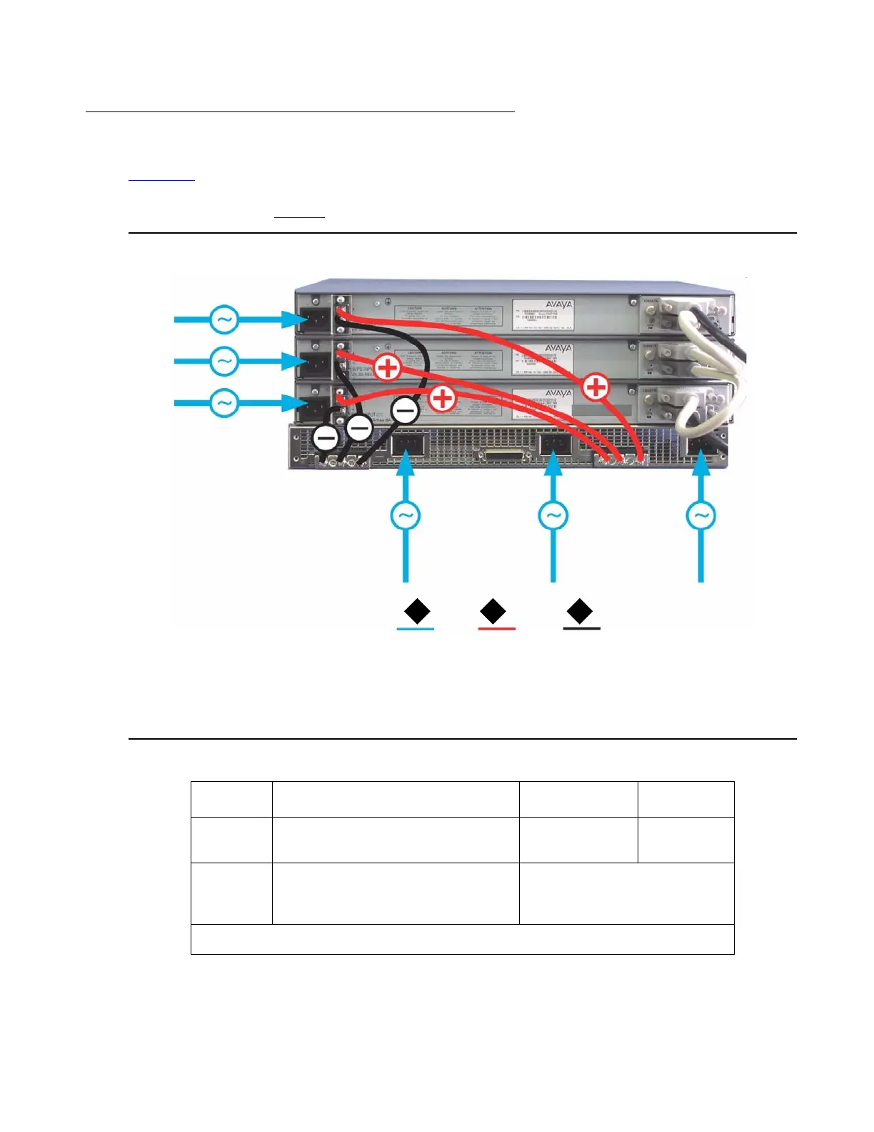
Sample Backup Power Supply Scheme
Figure 16 shows a connection example for a stack of three C363T-PWR switches. This
configuration provides power supply redundancy and up to 305 W of inline power per
C363T-PWR switch. Table 9
lists the equipment required for this scenario.
Figure 16: Sample Scheme
Figure notes:
1. AC power
2. BUPS DC input (+)
3. BUPS DC input (-)
Table 9: Required Equipment (C363T-PWR Scheme) 1 of 2
Quantity Description Material code PEC Code
3 C363T-PWR Power over
Ethernet Stackable Switch
700305881
1 APC (Advanced Power
Conversion PLC) Front End
AC-DC Power Shelf
APC-R2400A111*
1 of 2
2 31