Avaya C360 Front and Rear Panels
32 Installation and Configuration Guide Avaya C360 Multilayer Stackable Switches, version 4.5
C360 Front Panels
The front panel contains LEDs, controls, and connectors. The status LEDs and control buttons
provide at-a-glance information.
The front panel LEDs consist of Port LEDs and Function LEDs. The Port LEDs display
information for each port according to the illuminated function LED. The function is selected by
pressing the left or right button until the desired parameter LED is illuminated.
For example, if the COL LED is illuminated, then all Port LEDs show the collision status of their
respective port. If you wish to select the LAG function, then press the left button until the LAG
Function LED is lit; if you then wish to select Rx then press the right button three times until the
Rx function LED lights.
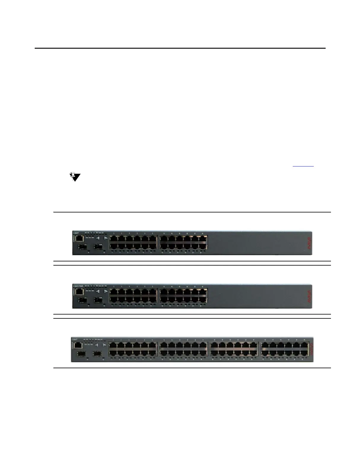
The front panels shown below includes LEDs, buttons, SFP GBIC transceiver housings,
10/100BASE-T ports and the RJ-45 console connector. The LEDs are described in Table 3
.
Tip:
Tip: The 10/100BASE-T ports of the C363T-PWR are numbered from 1 to 24; on the
C364T-PWR 1 to 48. The two SFP Gigabit Ethernet ports are numbered 51 and
52.
Figure 1: C363T Front Panel
Figure 2: C363T-PWR Front Panel
Figure 3: C364T Front Panel