Avaya C360 Front and Rear Panels
34 Installation and Configuration Guide Avaya C360 Multilayer Stackable Switches, version 4.5
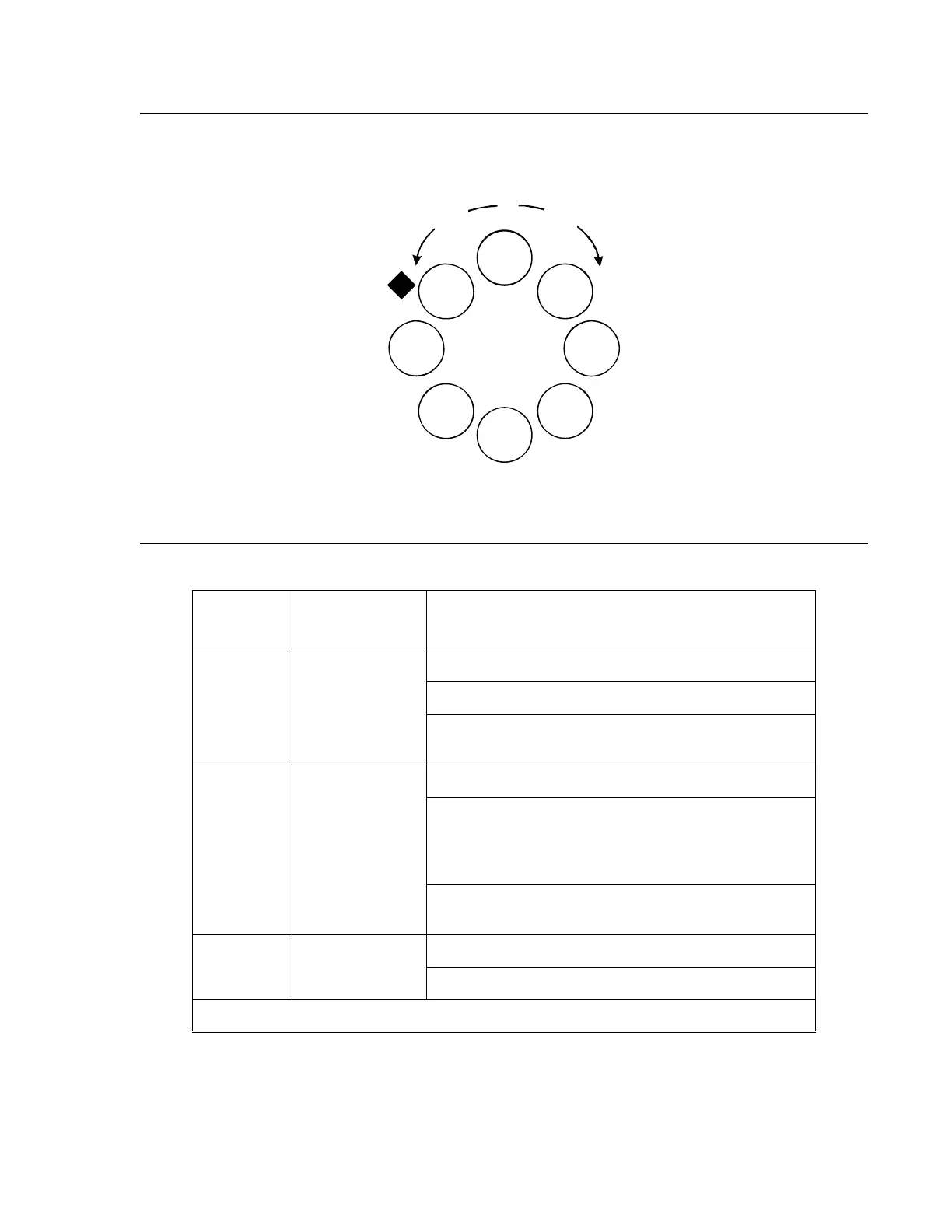
Figure 6: Order of Function 'Parameters Selected with the Left/Right Front Panel Buttons
Figure notes:
1. PoE LED on C360-PWR only
Table 3: C360 Function LED Descriptions 1 of 3
LED
Name
Description LED Status
PWR Power Status OFF - Power is off
ON - Power is on
Blinking - Main power is down and BUPS is
active
SYS System Status OFF - Module is a slave in a stack
ON - Module is the stack master, and the optional
Octaplane and Redundant cable(s) are either not
connected or not active.
This LED will also light in Standalone mode.
Blinking - Switch is the stack master and the
Octaplane is in redundant cable is active.
ROUT Routing Mode OFF - Layer 2 mode
ON - Router mode
1 of 3
Left
Button
Right
Button
Starting Point
(after Power-up or Reset)
COL
Tx
Rx
FDX
Hspd
LAG
PoE
LNK
1