5-102
Chapter 5. DETAILED DESCRIPTION OF EACH FUNCTION
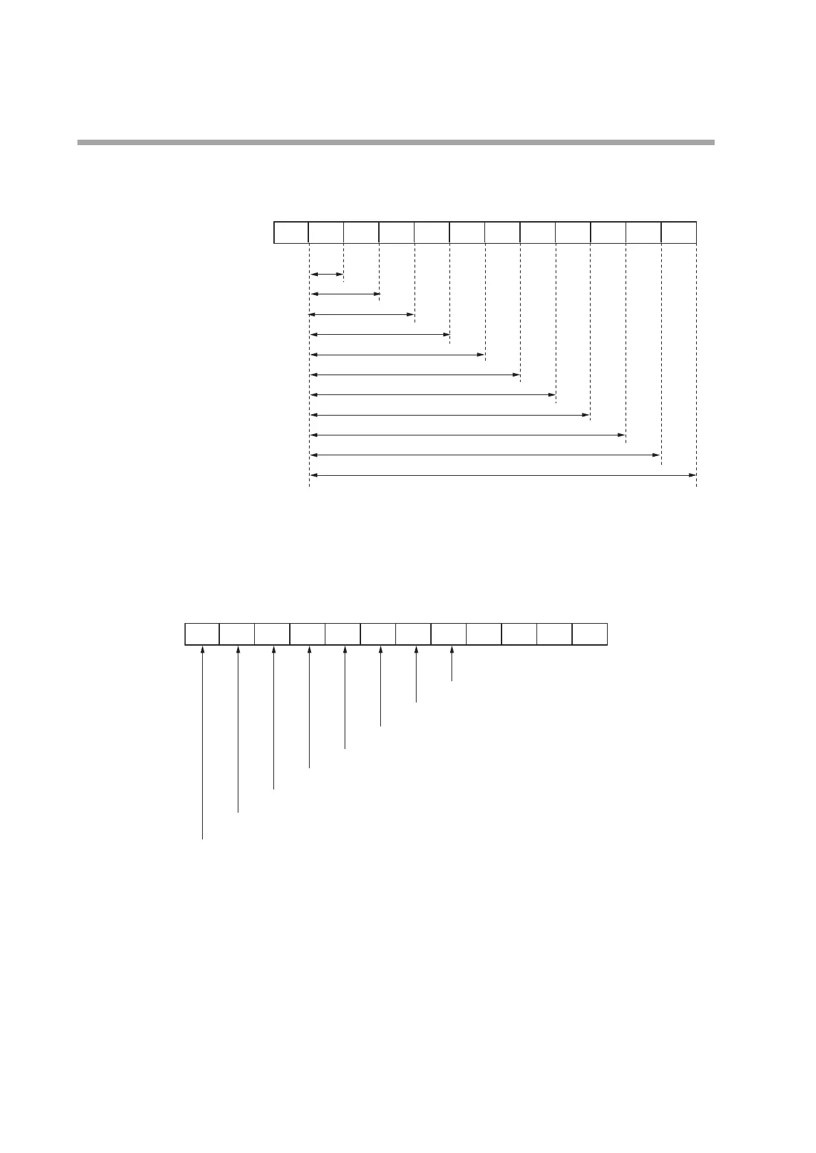
• When the lighting status is set at “9” (MV graph), “10” (Heat-side MV graph),
“11” (Cool-side MV graph), or “12” (MFB graph), the Multi Status (MS) display
is lit as shown in the following Figure:
Lighting range of MV graph (This explanation also applies to the heat MV, cool MV, and MFB.)
O at 0.0 % or less
0.1 to 10.0 %
10.1 to 20.0 %
20.1 to 30.0 %
30.1 to 40.0 %
40.1 to 50.0 %
50.1 to 60.0 %
60.1 to 70.0 %
70.1 to 80.0 %
80.1 to 90.0 %
90.1 to 100.0 %
100.1 % or more
• When the lighting status is set at “13” (DI monitor), “14” (Internal contact
monitor), or “15” (Internal event monitor), the Multi Status (MS) display is lit as
shown in the following Figure:
Lighting of DI, internal contact, and internal event
Internal event 8
Internal event 7
Internal event 6
Internal contact 5, internal event 5
DI 4, internal contact 4, internal event 4
DI 3, internal contact 3, internal event 3
DI 2, internal contact 2, internal event 2
DI 1, internal contact 1, internal event 1
 Loading...


