6-10
Chapter 6. LIST OF DISPLAYS AND SETTING DATA
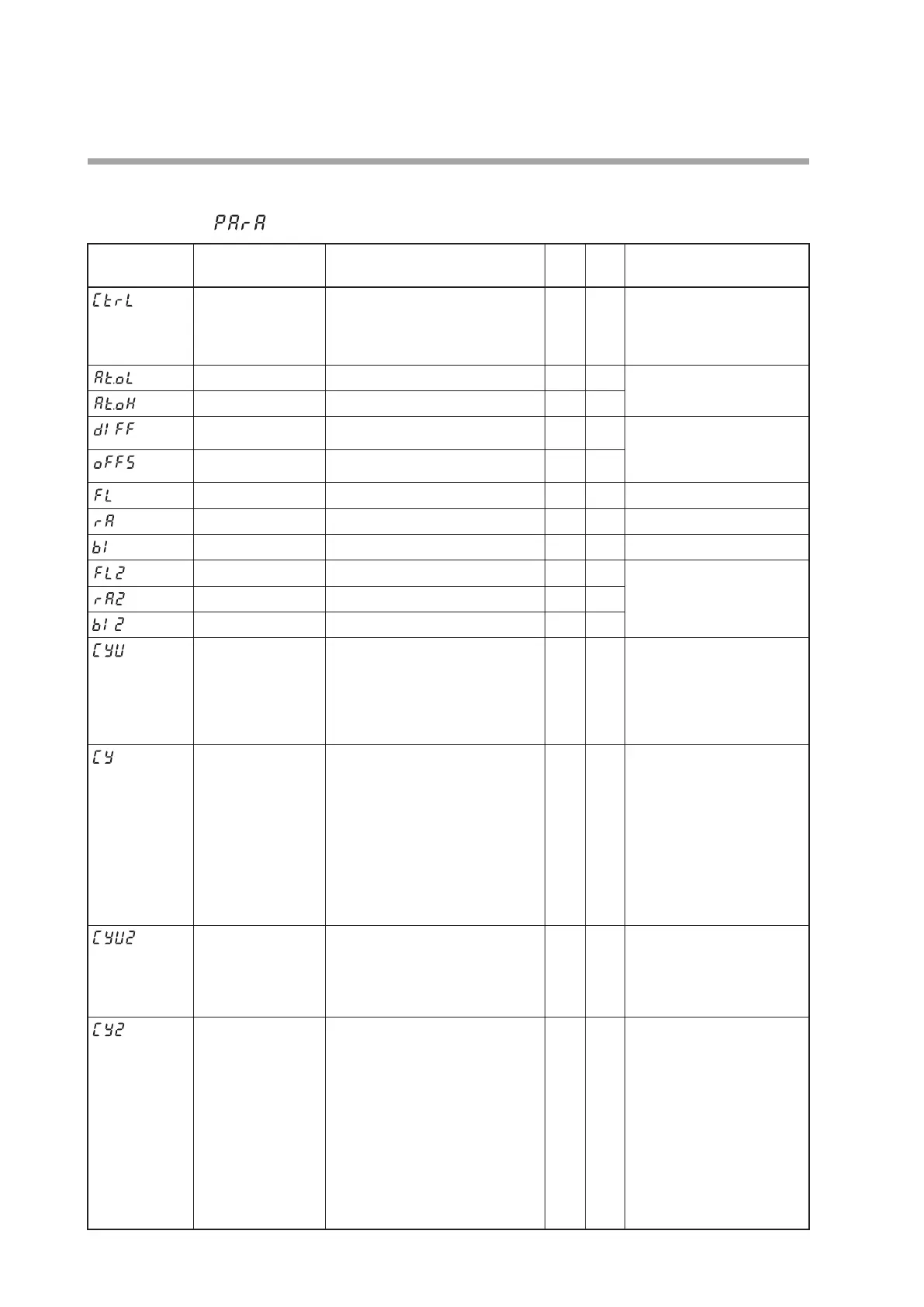
Parameter bank
Bank selection:
Display Item Contents
Initial
value
User
level
Notes
Control method 0: ON/OFF control
1: Fixed PID
0
or
1
0
The initial value is “0” when
the control output uses only
one point and is the relay
output. The initial value is “1”
in other cases.
MV low limit at AT -10.0 to +110.0 %
0.0 0
Displayed when the control
method is other than the ON/
OFF control (
CtrL
≠0).
MV high limit at AT -10.0 to +110.0 %
100.0 0
ON/OFF control
differential
0 to 9999 U
5 0
Displayed when the control
method is the ON/OFF control
(
CtrL
=0).
ON/OFF control
operating point offset
-1999 to +9999 U
0 2
PV filter 0 to 120.0 s
0.0 0
PV ratio 0.001 to 9.999
1.000 1
PV bias -1999 to +9999 U
0 0
RSP filter 0.0 to 120.0 s
0.0 1
Displayed when the model
provides the RSP input.
RSP ratio 0.001 to 9.999
1.000 1
RSP bias -1999 to +9999 U
0 1
Time proportional
cycle unit 1
0: 1 s unit
1: Cycle fixed at 0.5 s.
2: Cycle fixed at 0.25 s.
3: Cycle fixed at 0.1 s
If the set value is other than “0”,
the time proportional cycle 1 (
Cy
)
cannot be set.
0 2
Displayed under the same
conditions as
CY
except that
a relay is not included in the
output.
Time proportional
cycle 1
5 to 120 s (Output destination of
MV1 includes the relay output.)
1 to 120 s (Output destination of
MV1 does not include the relay
output.)
If the time proportional cycle unit
1 (
CyU
) ≠ 0, this setting becomes
invalid and the setting becomes
impossible.
10
or
2
0
Displayed when MV1 (time
proportional output (heat)
of Heat/Cool control) is
connected to the relay control
output, voltage pulse output,
or event output in the DO
Assignment.
The initial value of time
proportional cycle 1 is “10”
when the control output is
the relay output. The initial
value is “2” in other cases.
Time proportional
cycle unit 2
0: 1 s unit
1: Cycle fixed at 0.5 s.
2: Cycle fixed at 0.25 s.
3: Cycle fixed at 0.1 s
If the set value is other than “0”, the time
proportional cycle 2 (
Cy2
) cannot be set.
0 2
Displayed under the same
conditions as
CY2
except that
a relay is not included in the
output.
Time proportional
cycle 2
5 to 120 s (Output destination of
MV2 includes the relay output.)
1 to 120 s (Output destination of
MV2 does not include the relay
output.)
If the time proportional cycle unit
2 (
CyU2
) ≠ 0, this setting becomes
invalid and the setting becomes
impossible.
10
or
2
0
Displayed when the Heat/
Cool control is used (
C26
=1)
and MV2 (time proportional
output (cool) of Heat/Cool
control) is connected to the
relay control output, voltage
pulse control output, or event
output.
The initial value of time
proportional cycle 2 is “10”
when the model has one
control output point. The
initial value is “2” in other
cases.
 Loading...


