3-57
Chapter 3 Starting and Stopping this Device
(ii)
If the high pressure side flange is attached to the lower portion of the tank
This connection is possible with the JTE929S.
In addition, if the sealed liquid temperature compensation function is enabled, affix a minus sign
(-) to the height setting.
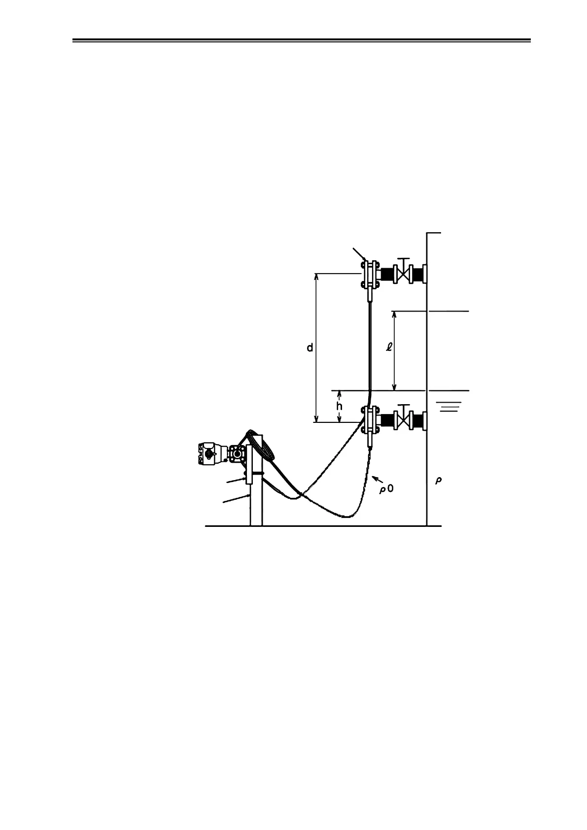
In this calculation, density and distance are represented by the following symbols. In addition,
density is assumed to be constant during liquid level measurement.
ρ: Specific gravity of liquid in tank
ρ
0
: Specific gravity of sealed liquid
l: Distance between the 100% liquid level and the 0% liquid level (measurement range)
h: Distance between the 0% liquid level and the high pressure side mounting flange
d: Distance between the flanges
High Pressure
Side Mounting
Flange
100%
Liquid Level
0%
Liquid Level
Low Pressure
Side Mounting
Flange
Mounting
Bracket
Pipe
Stanchion
Sealed
Tank
Figure 3-21. Sealed Tank (Wet Leg)
0% liquid level differential pressure
LRV = h×ρ - d×ρ
0
100% liquid level differential pressure
URV = l×ρ+h×ρ - d×ρ
0
= (l+h)×ρ - d×ρ
0
Accordingly,
Low limit (LRV): hρ - dρ
0
High limit (URV): (l+h)ρ - dρ
0
is the range to set.
 Loading...