2-16
Chapter 2 Installation of this Device
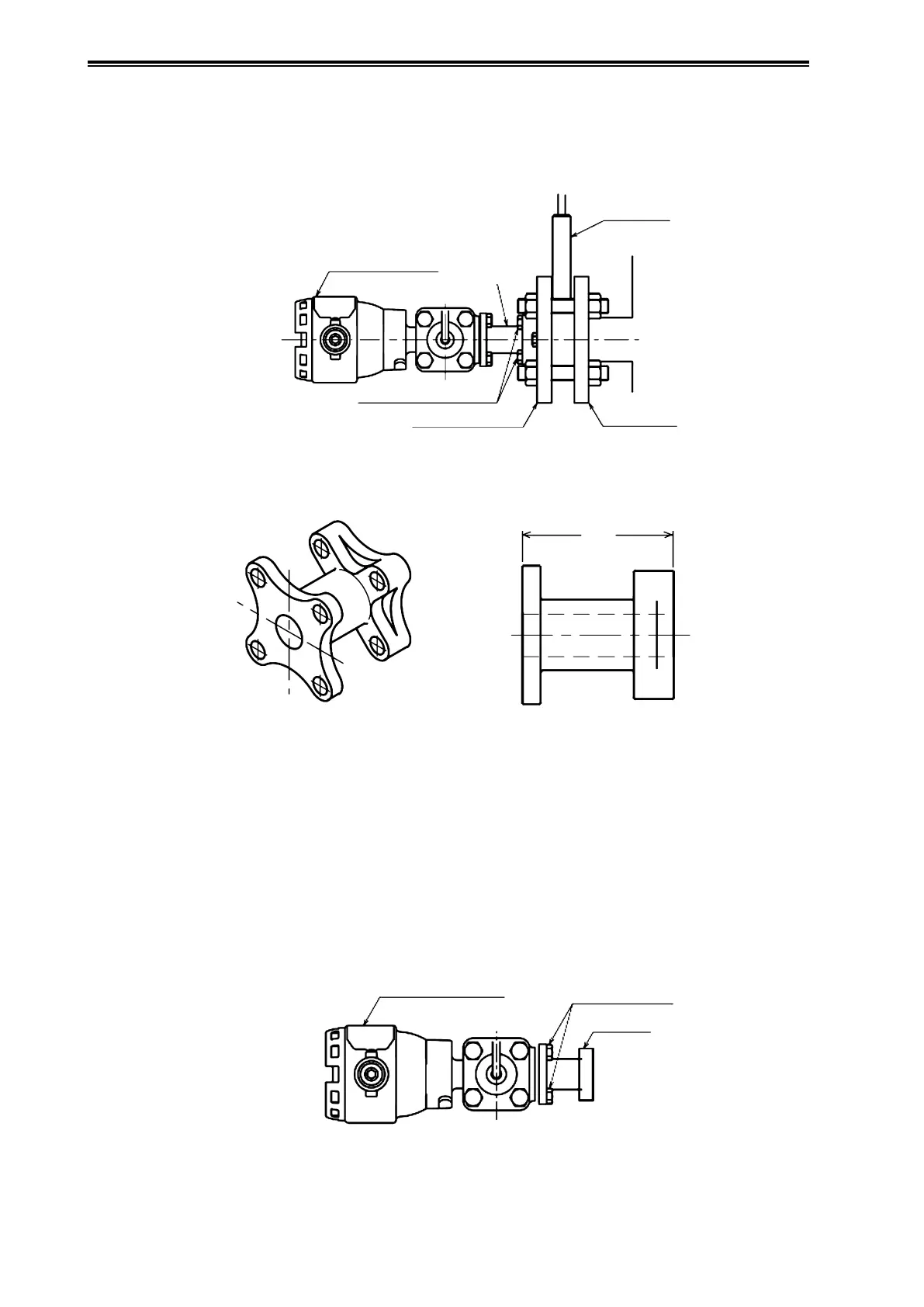
(2) Attachment Overview
(i) Attachment dimensions
Figure 2-18 shows the adapter assembly attached to the process side, and Figure 2-19 shows the
appearance and length of the adapter in the attachment kit.
Protective Pipe
Process Side
Process Side
Flange
Adapter
Remote Seal Type Dierential
Pressure Transmitter
Adapter Fastening Bolts
Transmitter Side Flange
Figure 2-18. Adapter Assembly
64
Figure 2-19. Adapter Appearance
(ii) Attachment location
Refer to the important notes regarding general-purpose installation conditions in section 2-1-1.
(iii) Attachment method
(1) Check that the adapter is attached to the transmitter.
Confirm that the adapter is firmly attached to the transmitter with four bolts.
Dierential
Pressure Transmitter
Adapter
Adapter Fastening
Bolts
Figure 2-20. Adapter Attachment