2. CSE-200 Specifications
Status LED ring
The c olor of the LED at the front of the Bas e Unit give information on the status of the system.
LEDs behavior E xplanation
static red
• receiving content from the Buttons and streaming towards the display.
• pairing and software update o f the Button is done. You can now unplug the
Button from the Base Unit.
• during the first phase of the Base Unit boot process.
blinking whit e
• system is starting up (during the sec ond phase )
• Button pairing is in progress
• software update of the Base Unit
breathing white
• ECO standby mode
static w hite
• awake and ready (i.e. showing the welcome mess age on the display)
• pairing is done
red blinking
• an e rro r occurred
dark
• deep standby/off
Standby button
The button at the front of the Base Un it has a standby function o nce the Base unit is powered
• When the system is in normal operational m ode, a push make s the system goes to a pre-defined standby mode.
• When the system is in a standby mode, a push triggers the system to start up and to go to normal operational mode.
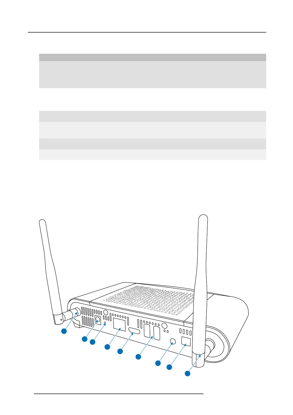
Back layout of the Base Unit
The connection panel is situated at the back of the Base unit.
2
3
1
1
4
5
6
8
7
Image 2-3
Backside B ase Unit
8 R5900023 CSE-200 11/04/2016

 Loading...