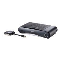
2. CSE-200 Specifications
1
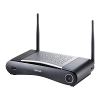
Fixture points for the antenna
2 Power connection
3 Reset
4 LAN Ethernet c onnection
5
HDMI connector
6
USB port
7
Analog Audio out
8 Digital Audio out
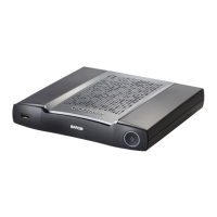
Mechanical fixture points
The mechanical fixture points are loc ated at the bottom of the Base Unit
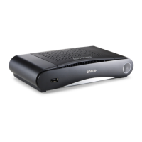
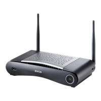
Antenna
Two antennas are included in the CSE-200 box. To avoid damage during transport, they are not pre-mounted.
The antennas can rotate for a better w ireless connection.
Usage of antennas other than the ones provided with the unit are allowed within the restrictions on usage of other antennas defined
by local regulations. Barco does not take responsibility for damage or disturbance of other de vices that may be caused by using a
diffe rent antenna. The use of a n active power amplifier is not allowed.
Antenna type : Dipole
Gain : Maximum 2 dBi peak gain in 2.4GHz an d 5Ghz band
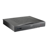
Bottom layout of the Base Unit
The serial number label containing the Barco part num ber, the revision n
umber, production date ( week-year) and the serial num ber.
The product label with the applicable certification logos .
The product label contains:
• the Barco logo
• the product name
• the Barco part number
• the power rating
• markings for applicable standards (CE, CCC, UL, ...)
• markings for waste regulation
• “Made in ...”
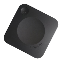
2.4 About the Button
Button
A Button toggles the sharing of the individual PC or MA C screen on the meeting screen.
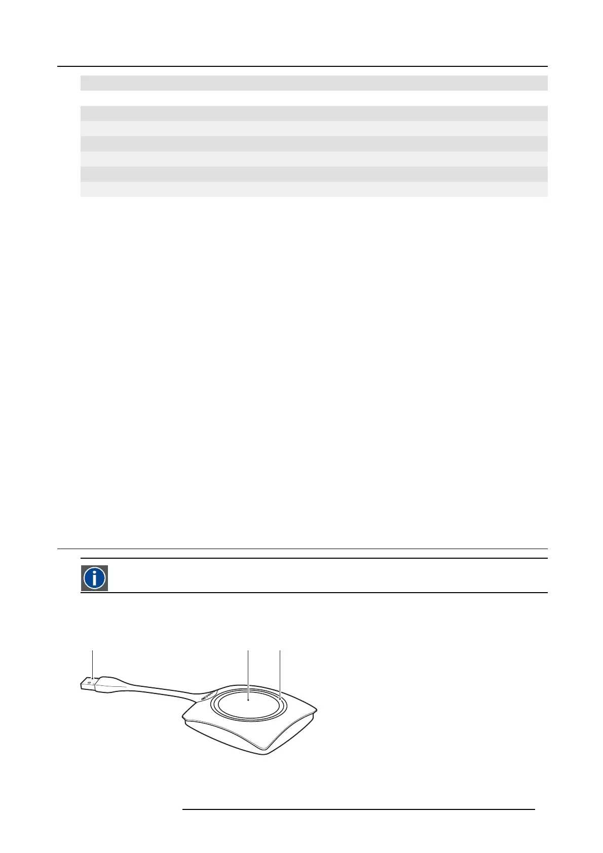
Button layout
A Button consists of three main components.
1 2 3
Image 2-4
Button layout
R5900023 CSE-200 11/04/2016 9
 Loading...