B. Pin configurations
GPO 5-8
Definition
RJ-45 pin
EXT_GPOU T_6_P
3
EXT_GPOU T_6_N
4
EXT_GPOU T_7_P
5
EXT_GPOU T_7_N
6
EXT_GPOU T_8_P
7
EXT_GPOU T_8_N
8
General Purpose Input:
GPI 1-4
Definition RJ-45 pin
EXT_GPIN_1_P 1
EXT_GPIN_1_N 2
EXT_GPIN_2_P 3
EXT_GPIN_2_N 4
EXT_GPIN_3_P
5
EXT_GPIN_3_N 6
EXT_GPIN_4_P
7
EXT_GPIN_4_N 8
GPI 5-8
Definition RJ-45 pin
EXT_GPIN_5_P 1
EXT_GPIN_5_N 2
EXT_GPIN_6_P 3
EXT_GPIN_6_N 4
EXT_GPIN_7_P
5
EXT_GPIN_7_N 6
EXT_GPIN_8_P
7
EXT_GPIN_8_N
8
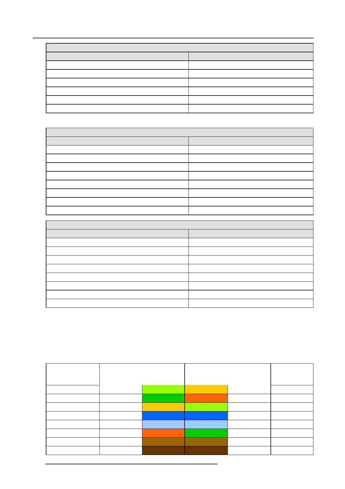
About 568A and 568B on an Ethernet connector
RJ-45
TIA/EIA-568A and -568B are two standards for connecting Category 3 and Category 5 wire to connectors. Both are appropriate for
high s peed d ata, though 568B is somew hat more comm on for installed wiring and 568A is more com mo n in jumpers. There is no
performance advan tage either way. The only real difference between the two is the order in which the pairs are us ed (orange and
green).
Hold a c able as if to plug it into a w all jack, the locking tab down (contacts facing you). The contacts are numbered 1-8 from left to
right. Here’s what you w ill see:
RJ-45 P in Number
(Left >Right copper
side)
568A 568B AES -1-8
1
White/Green White/Orange A ES 1&2 +plus
2
Green Orange AES 1&2 +minus
3
White/Orange White/Green A ES 3&4 +plus
4 Blue Blue
AES 5&6 +minu s
5
White/Blue White/Blue AES 5&6 +plus
6
Orange Green AES 3&4 +minus
7
White/Brown White/Brown AES 7&8 +plus
8Brown Brown
AES 7&8 +minu s
156 R5906847 DP2K SLP SERIES 02/06/2017

 Loading...


