R5906788-03 Thor series 113
Image 11-2
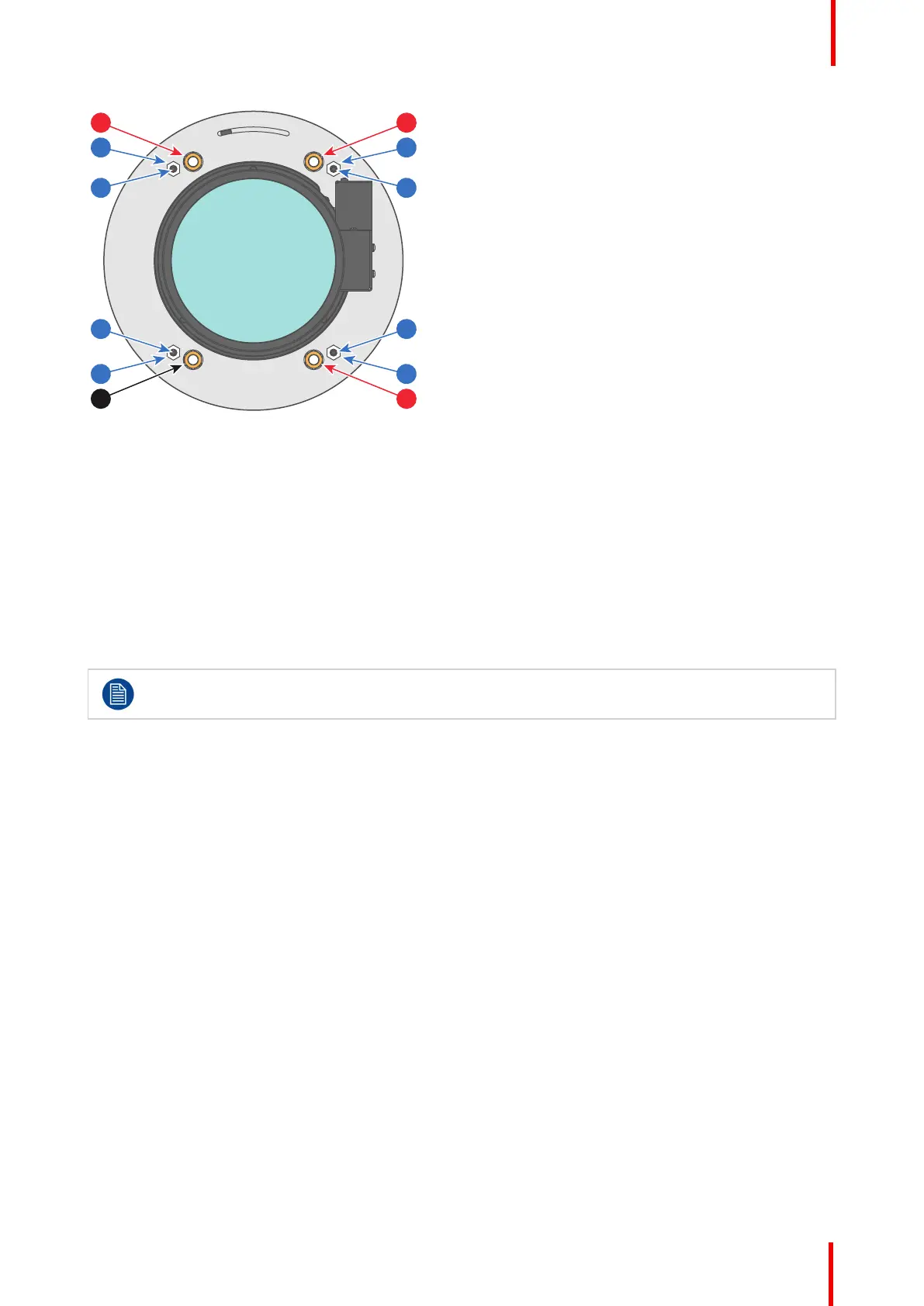
1 Scheimpflug adjustment nuts No1: Influences
the sharp focus plane in the lower left corner of
the projected image.
2 Scheimpflug adjustment nuts No2: Influences
the sharp focus plane in the lower right corner of
the projected image.
3 Scheimpflug adjustment nuts No3: Influences
the sharp focus plane in the upper right corner of
the projected image.
4 Scheimpflug nut No 4: without adjustment
functionality.
11 Lock nut.
12 Set screw for nut No1.
21 Lock nut.
22 Set screw for nut No2.
31 Lock nut.
32 Set screw for nut No3.
41 Lock nut.
42 Set screw for nut No4.
Reference 1, 2 and 3 are adjustment points. Reference 4 is a locking point and NOT used during
Scheimpflug adjustment.
When to apply Scheimpflug?
Only apply a Scheimpflug correction in case the overall focus of the projected image is not equally sharp (can
be caused if the projector is NOT in parallel with the screen or a previous misaligned Scheimpflug) . Take into
account that the consequence of applying Scheimpflug correction upon a screen not in parallel with the
projector is that the projected image differs from the rectangle shaped image. In other words “distortion” of
the projected image occurs. Masking will be required to solve the distortion.
The disadvantage of Masking is loss of content. Therefore it is strongly recommended to place the projector
in parallel with the projection screen and use the SHIFT functionality of the Lens Holder to match the
projected image with the projection screen. In case the SHIFT range is not sufficient then the projector can be
tilted and Scheimpflug can be applied.
11.2 Scheimpflug adjustment
Required tools
• Allen wrench 3 mm
• Nut driver 13 mm
• Nut driver 10 mm
Preparation steps:
1. Ensure that the throw ratio of the installed lens matches the requirements of the application (projection
distance and screen size).
Scheimpflug
 Loading...