R5906788-03 Thor series128
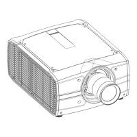
Image 12-6
4. Repeat from step 1 until full coincidence is obtained of the RED pattern in the center, left and right of the
projected image.
5. To adjust the green pattern. See procedure “Converging the green pattern onto the blue pattern”, page 128.
6. When the red and green pattern are overall aligned with the blue reference pattern install the cover plate of the
convergence control knobs and the projector left side cover.
12.4 Converging the green pattern onto the blue
pattern
This adjustment procedure assumes that the projector is prepared for convergence adjustment. See
chapter “Preparing for convergence adjustment”, page 126.
Required tools
5.5 mm nut driver or open-end wrench.
Converging the GREEN pattern onto the BLUE pattern
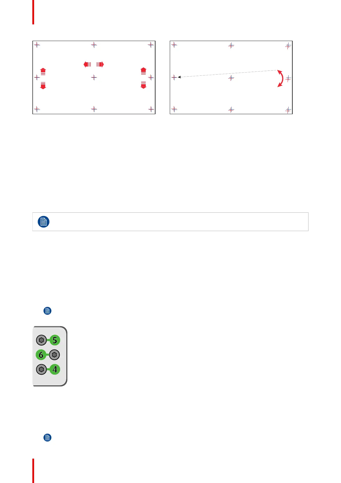
Start with aligning the GREEN pattern in the vertical direction (control knob 4 and 5) and then proceed
with the horizontal direction (control knob 6)
1. To translate the GREEN pattern vertically, slightly turn the green control knobs number 4 and 5. Turn both
control knobs in equal increments.
Note: Note that a turn of a few degrees corresponds with one full pixel. Turning the control knob
clockwise corresponds to the direction of the arrow of the test pattern.
Image 12-7
2. To translate the GREEN pattern horizontally, slightly turn the green control knob number 6.
3. To rotate the GREEN pattern, sightly turn the green control knob number 4. If much rotation is required,
slightly turn the green control knob number 5 in the opposite direction.
Note: Slight corrections of the GREEN pattern in vertical direction may be required after rotation.
Convergence
 Loading...