R5906788-03 Thor series28
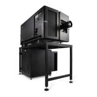
Component location
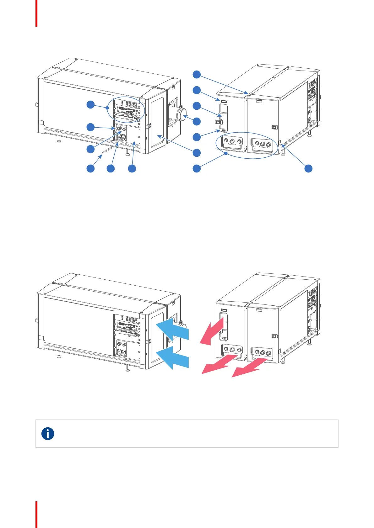
Image 3-3
1 Input & Communication interface.
2 Beam stop button.
3 Beam enable key.
4 Condensed water drain tubes.
5 UPS sockets.
6 Cover mains compartment.
7 Valve coupling to connect with external chiller(s).
8 Air inlet filter.
9 Communication port with chillers.
10 Lens.
11 Air outlet.
12 Projector status light.
13 Laser status light.
14 Projector ID label.
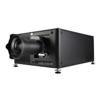
Air flow
The Thor series projector has two air flow channels (reference A & B) to cool the projector electronics. The air
intake is at the front side of the projector, the air outlet is at the back side.
Image 3-4
3.2 Chillers and hoses
DMD
A digital micromirror device, or DMD, is an optical semiconductor that is the core of DLP projection
technology.
System overview
 Loading...