commissioning (qualified
Handscanner
BCS 3600
ex
series
70 / 106
Subject to technical modifications
Revision A / 04/2019
7.2 Universal supply module
7.2.1 Establishing universal supply module connections
Non-approved accessories!
Loss of function and risk of explosion.
Only use universal supply modules that have been specified for the relevant configuration by
The approved accessories are shown in the system overview (see system overview, Chapter 15.2).
The model is clearly indicated on the type label.
The universal supply module is mounted to a secure base.
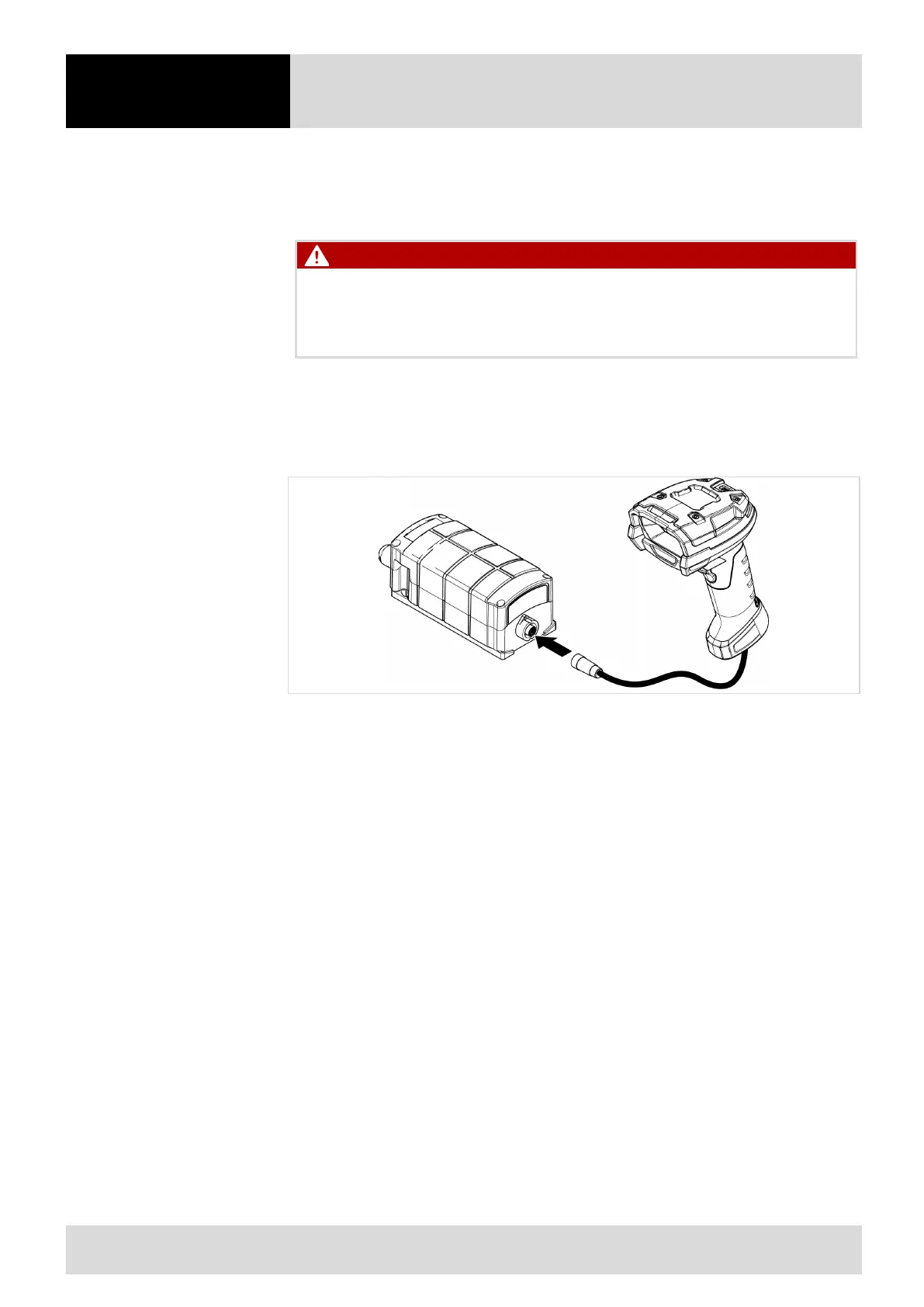
Figure 26 Mounting the hand-held scanner with the Universal Supply Module
1. When using the corded hand-held scanner: connect the connection cable of the hand-held
scanner to the USM, turning the connection cable clockwise to screw tight.
2. When using the Bluetooth hand-held scanner: connect the hand-held scanner via pairing to the
USM (see Chapter 6.4.1).
3. Feed the connection cable for the power supply through the cable gland into the USM.
4. Feed the data cable between the PC and universal supply module through the cable gland into
the USM.
5. Connect the connection cable for the power supply to the USM according to the terminal
connection plan (see Chapter 4.6.1).
6. Connect the data cable between the PC and USM to the USM according to the terminal connection
plan and interface type (see Chapter 4.6.1).
7. Check connections and terminal assignments.
8. Connect data cable between the PC and USM to the PC.
9. Set the DIP switch (see Chapter 4.6.2 for configuration).
10. Close the cover of the USM.
11. Connect the connection cable for the power supply to the power source.
12. For connection to an HID device or to a PLC: note further information on the interfaces (HID
device: see Chapter 7.2.2; PLC: see Chapter 7.2.3)