Camera Interface
2-6 Basler A500k Series
PRELIMINARY
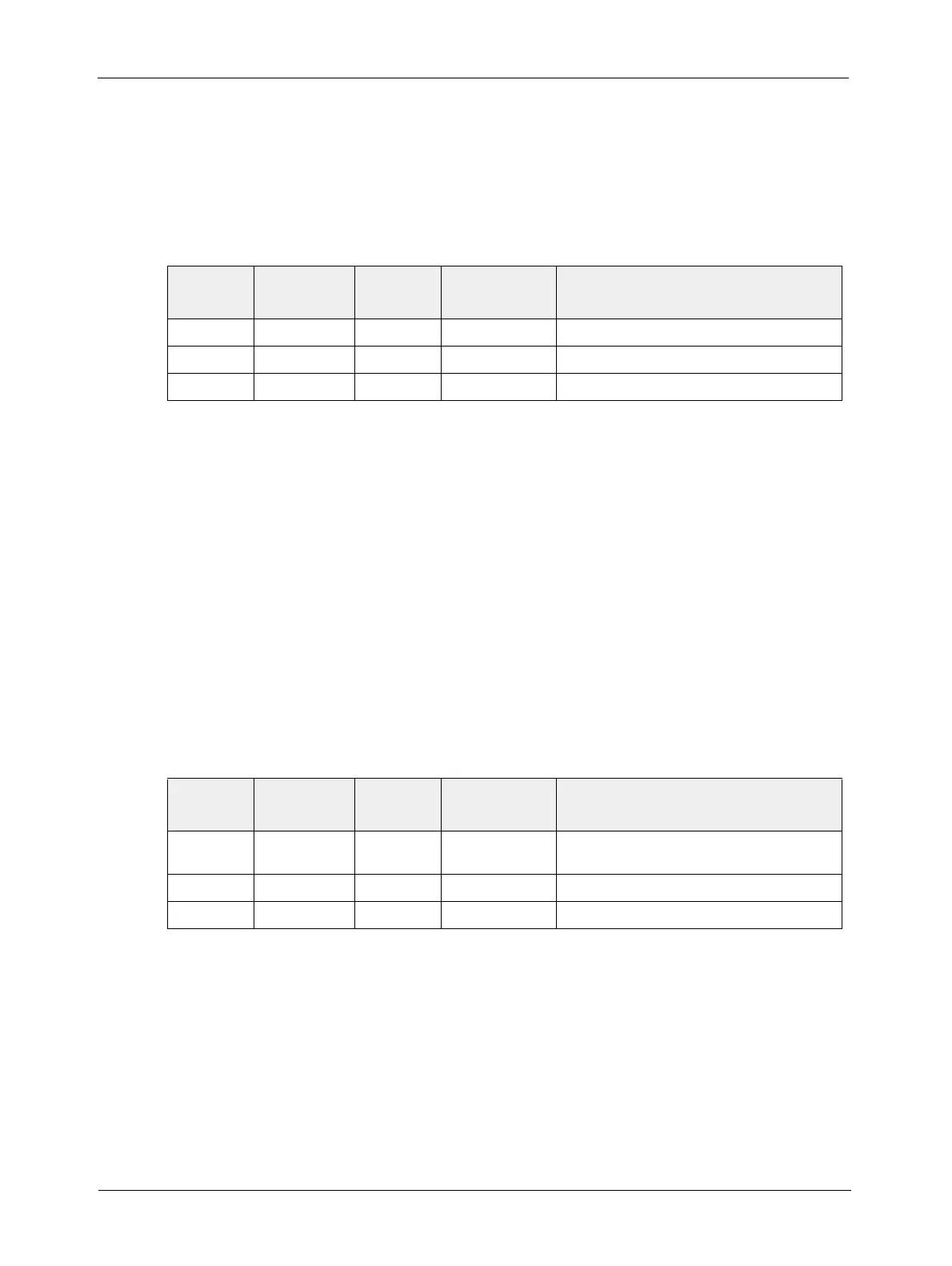
2.1.3 Pin Assignment for the Power Connector
The power input connector type is a microminiature push-pull lock type connector, the Hirose
HR 10A-7R-6PB. The power supply should deliver 12V at a minimum of 500 mA (
A504k/kc) or
250 mA (
A501k/kc) with a voltage accuracy of ±10%. The pin assignment of the plug is given in
Table 2-3.
You can use the Hirose HR 10A-7P-6S connector for your cable.
2.1.4 Pin Assignment for the Flash Trigger Receptacle
The Flash trigger output connector type is a microminiature push-pull lock type connector, the
Hirose HR 10A-7R-4S. The receptacle provides a TTL signal for an external flash. This signal can
be programmed via the FlashCtrl register. It can be deactivated, tied to an “effective exposure“
signal generated internally, tied to the external ExFlash input, and it can be permanently on.
The output signal can selected to be to TTL Active High (default setting), Low Side Switch (Open
Collector), or High Side Switch via the Flash Trigger Modes register (see section 4.2.4.14).
The pin assignment is given in Table 2-4. Figure 2-4 shows the three variants of output schematics
of the flash trigger connector.
You can use the Hirose HR 10A-7P-4P connector for your cable.
The FlashOut signal is short-circuit proof. The signal is electrically isolated from other signals in
the camera. See the timing diagram in Figure 2-3 and the flash trigger output schematics in Figure
2-4.
Pin
Number
Signal
Name
Direction Level Function
1, 2 +12 VDC Input 12 VDC ± 10% DC Power
3, 4
not connected
5, 6 DC GND Input Ground DC ground
Table 2-3:A500k Pin Assignment for the Power Receptacle
Pin
Number
Signal
Name
Direction Level Function
2 FlashOut Output TTL signal Flash trigger; the HIGH signal is current limited
to 50 mA ±20%.
1, 3
not connected
4 DC GND Output Ground DC ground
Table 2-4:A500k Pin Assignment for the Flash Trigger Receptacle