Basic Operation and Features
Basler A500k Series 3-29
PRELIMINARY
3.7 Gain and Offset
The major components in the A500k electronics
include: a CMOS sensor, which includes 1024 ADCs
(Analog to Digital Converters), and a digital shifter.
The pixels in the CMOS sensor output voltage signals
when they are exposed to light. After readout of the
pixel voltage, an offset is added to each voltage. The
voltages are then transferred to the ADCs which
convert the voltages to digital output signals. The ADC
reference is used to set the gain, but only in a small
range. The 10 bit data from the ADCs in the sensor
enters the digital shifter in the camera electronics
where the 8 bits to be output are selected from the 10
bits output by the sensor.
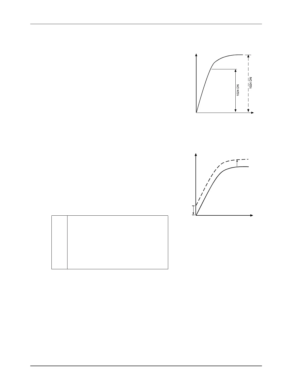
As shown in Figures 3-26 and 3-27, the gain is increased or decreased by decreasing or
increasing the ADC reference. Increasing or decreasing the offset moves the input signal up or
down the measurement scale but does not change the signal amplitude.
For most applications, black should have a gray value
of 1 and white should have a gray value of 254.
Attempt to achieve this by varying exposure and
illumination rather than changing the camera’s gain.
The default gain (gain register = 98) is the optimal
operating point (minimum noise) and should be used if
possible.
The gain can either be changed via the corresponding
ADC reference which can be set in the gain register, or
by selecting different bits in the digital shifter.
In order to obtain a higher gain factor of up to 8, use the digital shift in combination with the gain
register (for an explanation of the digital shifter, see section 3.8.).
You can set the gain and offset using either the Camera Configuration Tool Plus (see Section 4.1)
or binary commands (see Section 4.2).
*
Raising the gain via the ADC reference has
the consequence that noise is increased so
that the signal-to-noise ratio decreases. In
addition, missing codes may degrade the
image quality severely. We recommend that
you do not change the gain via the ADC ref-
erence. The default gain register setting is
98.
input
signal
to ADC
[V]
light intensity [
µ
J/cm
2
]
increasing gain
by decreasing
the ADC reference
ADCREF
ADCREF
Figure 3-26:
increasing/
decreasing offset
moves the input
signal up/down the
measurement scale
negative
offset
input
signal
to ADC
[V]
light intensity [
µ
J/cm
2
]
positive
offset
Figure 3-27: Offset