Basic Operation and Features
3-28 Basler A500k Series
PRELIMINARY
3.6 Color Creation in the A504
A504A504
A504kc and A501
A501A501
A501kc
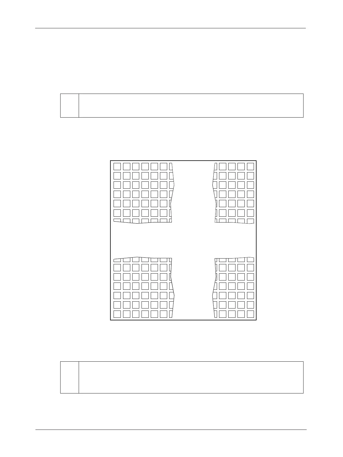
The CMOS sensor used in the color version of the camera is equipped with an additive color
separation filter. With the color filter, each individual pixel is covered by a micro-lens which allows
light of only one color to strike the pixel. The pattern of the color filter is shown in Figure 3-25. As
the figure illustrates, in each block of four pixels, one pixel is struck by red light, one is struck by
blue light and two pixels are struck by green light.
Since each individual pixel gathers information on only one color, an interpolation must be made
from the surrounding pixels to get full RGB data for the pixel. A DLL that can be used to convert
the output from the color camera into RGB color information is available through Basler support.
Figure 3-25: Bayer Filter Pattern
*
The pattern used in the A504kc and the A501kc is that of the Bayer Filter. The first line,
however, is different: it starts with GR and not with BG.
*
IR Cut Filter
In applications using the normal range of visible light we recommend that you plug an
IR cut filter in front of your F-mount lens.
B
RGRGRG
GBGBG
RGRGRG
RGRGRG
BGBGBG
BGBGBG
B
RGRGRG
GBGBG
RGRGRG
RGRGRG
BGBGBG
BGBGBG
RGRG
BGBG
RGRG
RGRG
BGBG
BGBG
RGRG
BGBG
RGRG
RGRG
BGBG
BGBG
Line 1
Line 2
Line 3
Line 4
Line 5
Line 6
Line 1020
Line 1021
Line 1022
Line 1023
Line 1019
Line 1024
123456 1280127912781277Pixel