Camera Interface
2-8 Basler A500k Series
PRELIMINARY
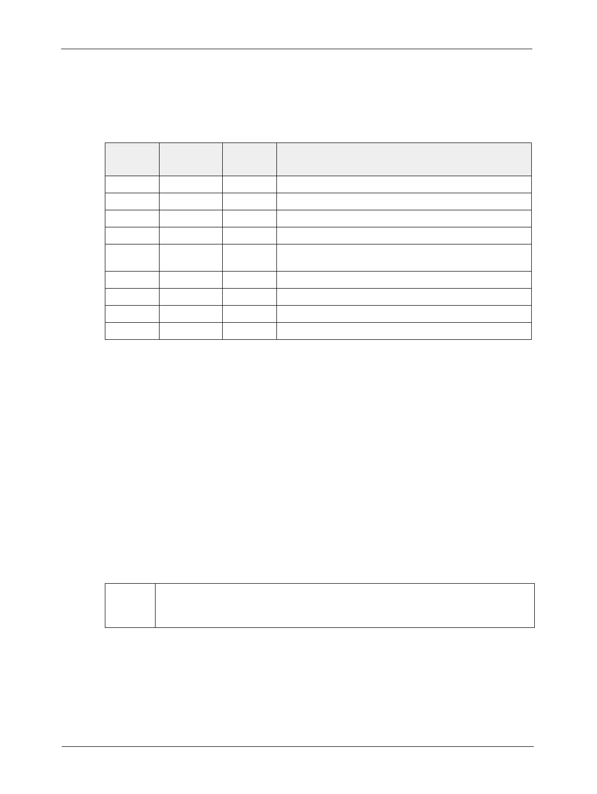
2.1.5 Pin Assignment for the VGA Monitor Output
(A504k/kc Only)
The 15 pin HDSub receptacle for the VGA monitor output transmits 640*480 pixels at a rate of 60
fps. The pin assignment is given in Table 2-1 and Table 2-2.
2.2 Cable Information
2.2.1 Camera Link Cable
The Camera Link specification requires the use of a standard MDR cable assembly manufactured
by 3M (part # 14X26-SZLB-XXX-0LC).
The maximum allowed length for the MDR cable used with an
A501k/kc is 7 meters. The maximum
allowed length for the MDR cable used with an
A504k/kc is 5 meters.
A Camera Link compatible MDR cable assembly is available from Basler as a stock item (part #
1000013905 for a 3 meter cable and part # 1000013906 for a 5 meter cable). Alternatively, you
can use the cable assembly manufactured by 3M (part # 14X26-SZLB-XXX-0LC). The
A501k/kc
can also use a base configuration Camera Link cable. See the cable information on the Basler
website www.baslerweb.com.
2.2.2 Power Cable
A Hirose, 6-pin locking plug will be shipped with each camera. This plug should be used to
terminate the cable on the power supply for the camera. For proper EMI protection, the power
supply cable attached to this plug must be a twin-cored, shielded cable. Also, the housing of the
Hirose plug must be connected to the cable shield and the cable must be connected to earth
ground at the power supply.
Pin
Number
Signal
Name
Direction Function
1 Red Video Output Red Video
2 Green Video
Output Green Video
3 Blue Video
Output Blue Video
4, 9 not connected
5, 6, 7, 8,
10, 11
DC Gnd Output DC Ground
12 not connected
SDA is not supported
13 HSync
Output HSync, 5 V TTL signal
14
VSync Output VSync, 5 V TTL signal
15
not connected SCL is not supported
Table 2-5: A504k/kc Pin Assignments for the VGA monitor output
*
The maximum cable length will decrease when used in an area with severe ambient
electromagnetic interference.