Camera Interface
2-22 Basler A500k Series
PRELIMINARY
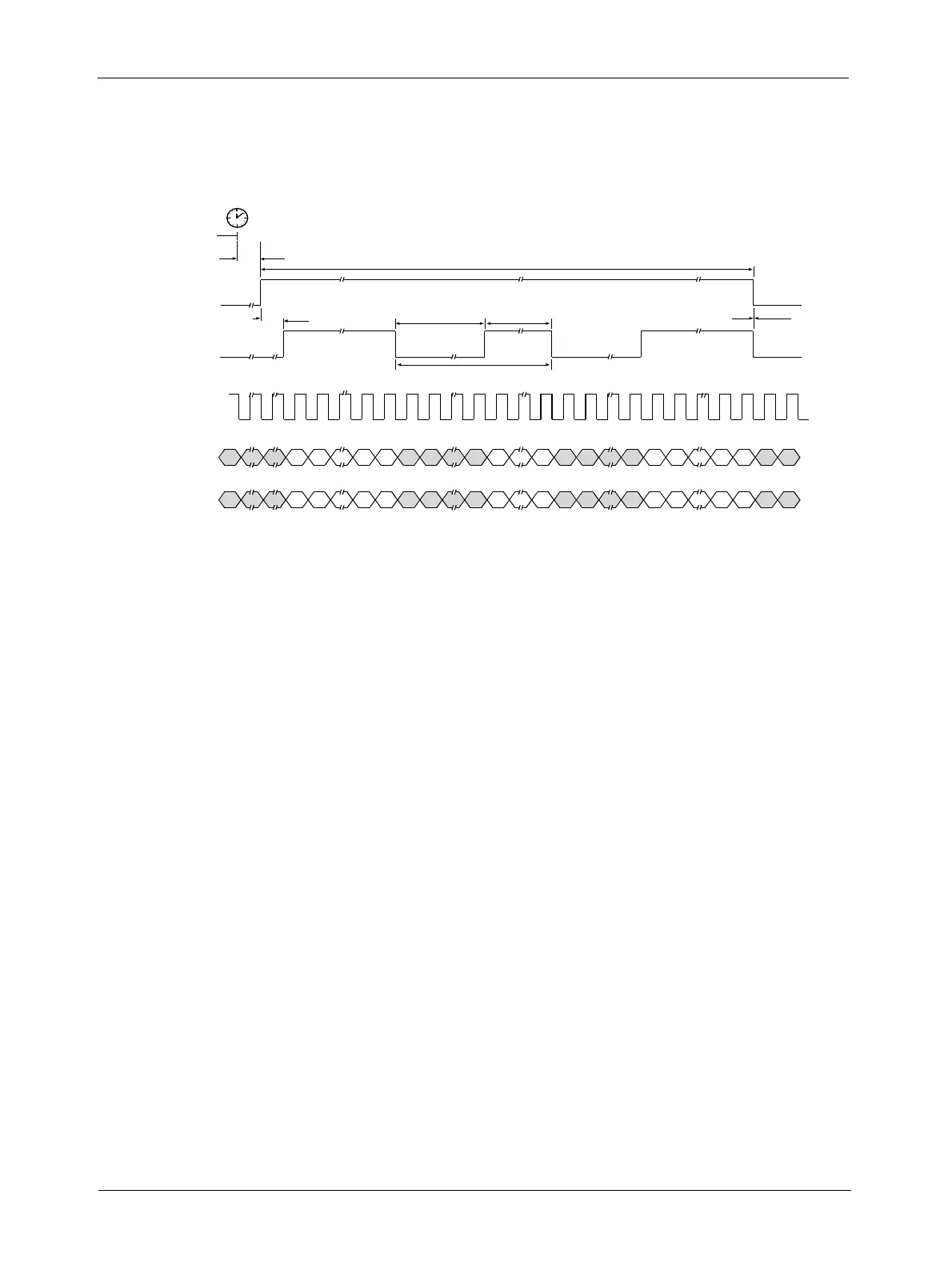
Figure 2-10: 8 Bit output Mode with Programmable Exposure for the A501k/kc
2.5.7 Flash Trigger Signal
This signal can be programmed via the FlashCtrl register (see section 4.2.4.14). Six different
options are programmable:
• The FlashOut trigger signal can be deactivated, that is, low.
• It can be tied to an “Effective Exposure“ signal that is generated internally. This means that
the FlashOut signal goes high when exposure starts and it goes low when exposure stops,
regardless of the exposure mode chosen. As an option, the polarity of FlashOut can be
inverted.
• The signal can be tied to the external ExFlash input signal provided by the framegrabber. As
an option, the polarity of FlashOut can be inverted.
• FlashOut can be permanently high.
This diagram assumes that the area of interest feature is not being used. With the area of interest feature enabled, the
number of pixels transferred could be smaller.
Frame
Valid
Line
Valid
Line 1 Line 2 Line 1024
Pixel
Clock
(50 MHz)
min. 3 µs
0.1 µs
0.4 µs 12.8 µs
13.2 µs
0 µs
13.517 ms
D_0
Pixel Data
(8 bits)
12771 127913
1279
1
1277 12791
D_1
Pixel Data
(8 bits)
12782 128024
1280
2
1278 12802
3
4
end of
programmed
time
..5
..5
1
12
2
20
20 1
12
2
20
20