A: R82GB0CA.PDM
B: R82DE0CA.PDM
E: 080403 / T. Wenger
G: 020403 / TCS
Section 3
Page 2
Specifications
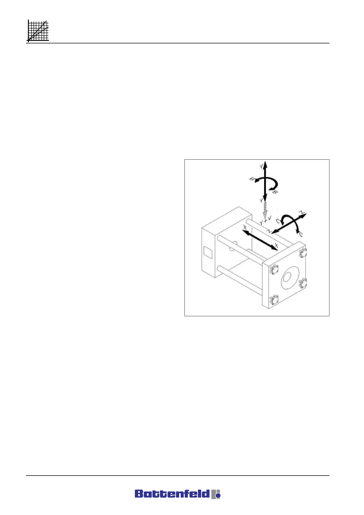
3.2 Robot axis definitions
The axes are defined according to a fixed
cartesian co-ordinate system made up of the
horizontal X and Z axes and the vertical Y axis.
Industrial robots are, in a broader sense,
numerically controlled machines. The axes are
therefore defined as in DIN 66 217.
Extensive use of DIN 66 025 creates a uniform
addressing system for the purpose of controlling
the axes.
3.2.1 Linear axes
The following linear and main axes are driven by
electric motors:
X main horizontal linear axis parallel to the
first axis of the reference co-ordinate
system (IMM longitudinal direction)
Z main horizontal linear axis parallel to the
second axis of the reference co-ordinate
system (IMM transverse direction)
Y main vertical linear axis parallel to the
third axis of the reference co-ordinate
system
3.2.2 Auxiliary axes
The following rotating and auxiliary axes are
pneumatically driven:
B auxiliary axis parallel to the Y-axis or
other main rotating axis
C auxiliary axis parallel to the Z-axis
The most common axes are shown in the ”Axis
definition” diagram below.
The axis letter symbols are positioned at
suitable, clearly visible points to indicate the type
and direction of movement of each axis.
R8B2_001.JPG