Assembly and Operation
A: R82GB0EA.PMD
B: R82DE0EA.PMD
E: 170403 /T. Wenger
G: 020403 / TCS
Section - 5
Page - 5
?
R8B2_015.PDF
4
3
1
2
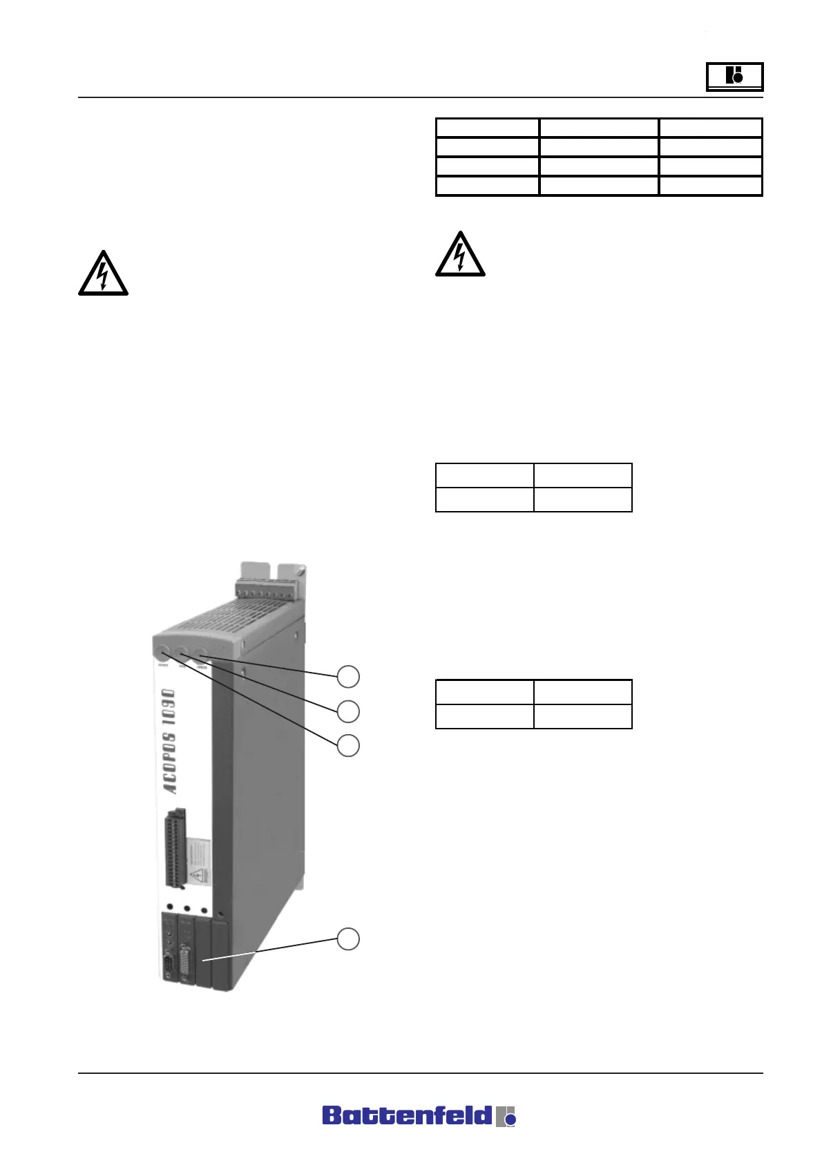
5.3.3 Terminal box 1
Terminal box 1 is located at the end of the main
axis support. It contains the servo booster as
well as the motors and sensor analysis change-
over.
Do not alter change the shielding on the
motor cables!
The fan inside the terminal box must be
switched on in order to prevent the ACOPOS
servo booster from overheating.
Basic design of the B&R 8V1090.00-2 servo
booster:
The LED is illuminated when the ACOPOS
servo booster is connected to the 24 V DC
power supply.
After switching off the devices the intermediate
circuit requires a discharge time of at least 5
minutes. Use a suitable measuring device to
check that the current intermediate circuit
voltage is below 24 V DC to ensure that the
system is safe before carrying out any work. If
the LED indicator is extinguished this does not
necessary mean that the device has been
deenergised!
Description:
Illuminated when the ACOPOS servo booster is
ready for operation and the power stage can be
activated. (Operating system available and
booted up, no permanent or temporary faults
detected).
Description:
Lights up when the ACOPOS servo booster
power stage is activated.
LED Description Colour
1 Ready green
2 Run orange
3Errorred
R8B2_GB016.XLS
Signal LED
Ready green
R8B2_GB130.XLS
Signal LED
Run orange
R8B2_GB131.XLS