Transport - Installation
A: R82GB0DA.PMD
B: R82DE0DA.PMD
E: 080403 / T. Wenger
G: 020403 / TCS
Section 4
Page 5
If no peripheral device is used or if there is
no service door, it is important that the
supplied dummy plugs for bypassing the
EMERGENCY STOP are connected.
The plugs can be clearly identified by the
coded sockets and pins.
4.3.3 Lubrication points
Check all lubrication points.
4.3.4 Compressed air supply
Connect the compressed air supply to the robot
service unit and adjust to 6 bar (87 psi). Refer to
Section 2.0 Safety, 2.1.5 Safety regulations –
Pneumatic systems.
4.3.5 Activate main switch
Activate the main switch on the control cabinet
to start the control system. The motors are
initially interrupted by the main fuse (40 K1).
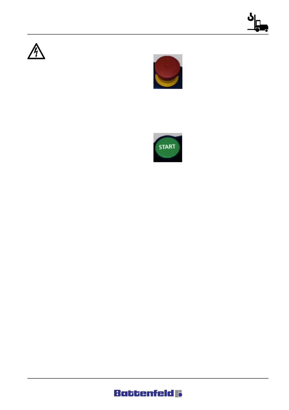
4.3.6 EMERGENCY STOP test
To test the EMERGENCY STOP
(hardware and software) on the
manual control device, press and
release the button. Also check that
all the other EMERGENCY STOP
devices (IMM, Periphery) are
released. This procedure must be repeated
each time the main switch is activated/
deactivated.
4.3.7 Power ON
After checking the EMERGENCY
STOP line and activating the slam
button, press the START button
together with the TOTMANN button
on the MCD and observe the robot
(visual check).
Once all the initial start-up steps have been
carried out, the main contactor (40 K1) activates
the power supply at the ACOPOS servo booster.
The motor holding brakes remain activated. The
three servo axes are not controlled. (Axis
sequencing)