A: R82GB0EA.PMD
B: R82DE0EA.PMD
E: 170403 /T. Wenger
G: 020403 / TCS
Section - 5
Page - 10
Assembly and Operation
?
5.4.2 PCS General
The CP476 B&R SYSTEMS 2003 comprises a
sophisticated central component of the robot
system.
Features:
750 kByte User SRAM
1.5 mByte User FlashPROM
CP interface with four module slots
Two node number switches
The CP476 central unit has a system bus for
additional expansion units. Two CAN node
number switches eliminate the need for offset
adjustments. The actual node number always
corresponds to the switch position.
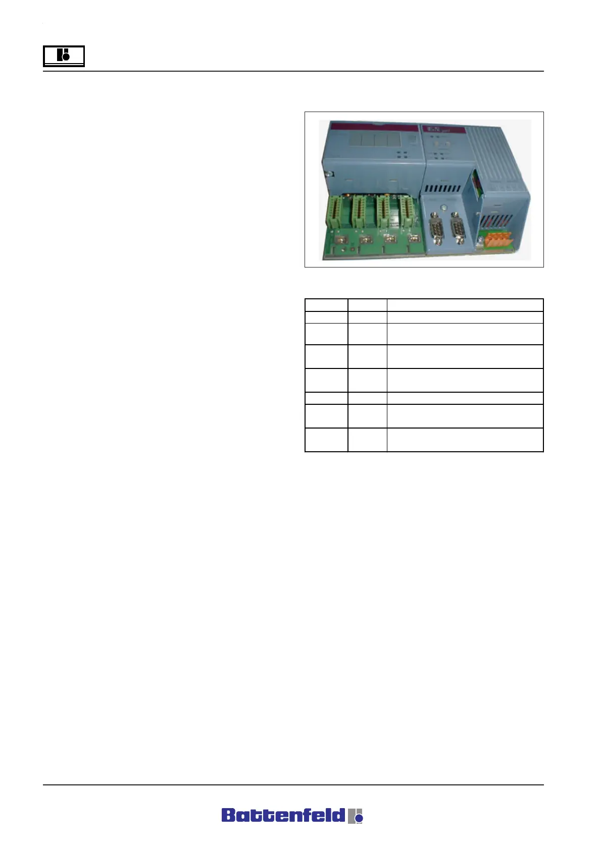
5.4.3 CP476 status display
R8B2_021.JPG
LED Colour Decription
CAN orange Data flow from/to CAN controller
RS232 orange
Indicates whether data are
received/sent
ERR red
Lights up in Service mode and if a
fault occurs
RUN green
Lights up in RUN and in Service
mode
RDY green Lights up in Service mode
MODE green
Lights up during FlashPROM
programming
1, 2, 3, 4 orange
LEDs indicate operating status of
each adapter module.
R8B2_GB023.XLS