A: R82GB0DA.PMD
B: R82DE0DA.PMD
E: 080403 / T. Wenger
G: 020403 / TCS
Section 4
Page 4
Transport - Installation
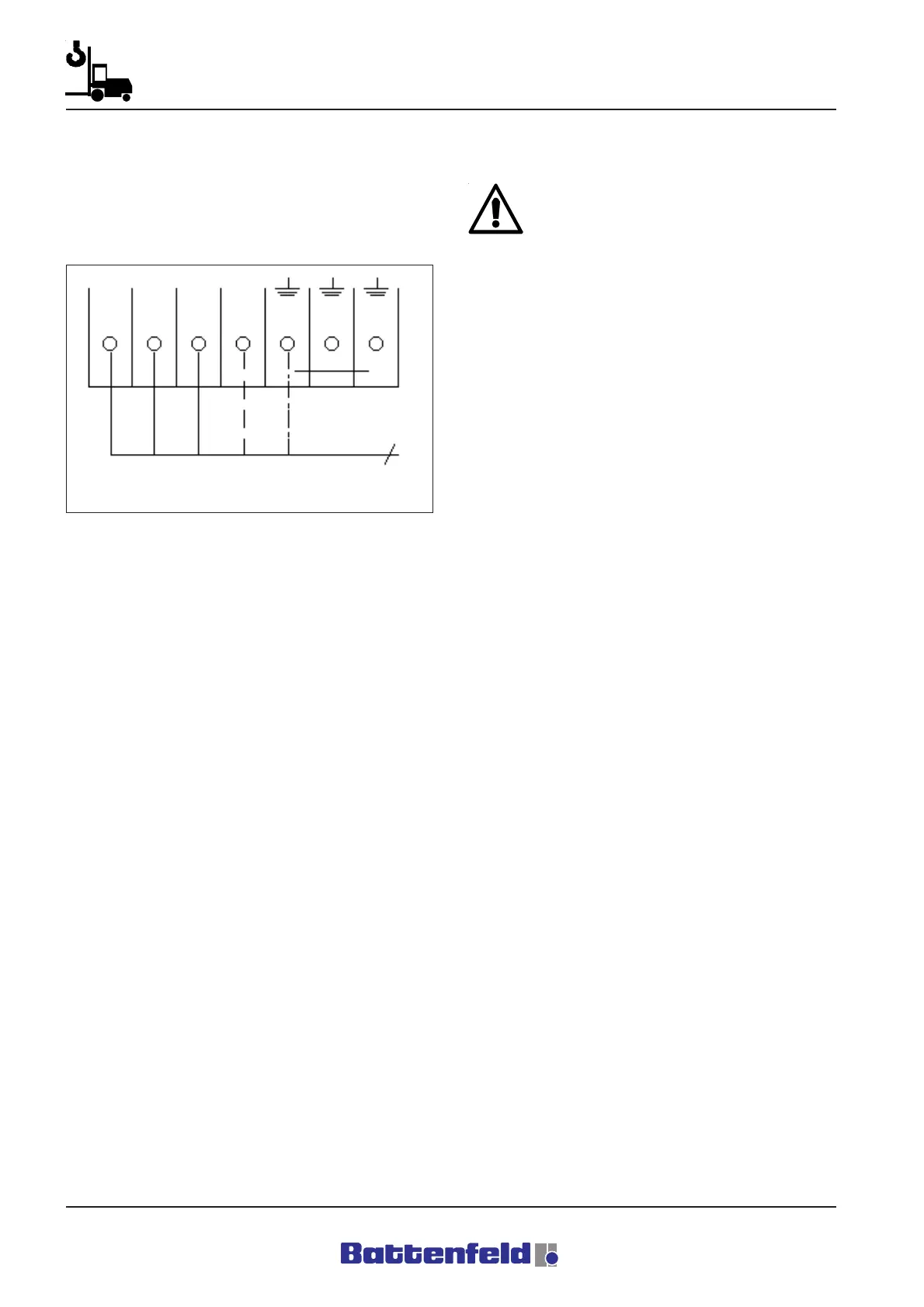
Attach the outer conductors to the terminals
inside the control cabinet.
Attachment type:
Feeder + neutral conductor
Main incoming supply. Refer to the circuit
diagram on Sheet B1. No.: 10
4.3. Commissioning
Before you start the commissioning
procedure, it is important to read and make
sure that you have understood all the items
contained in the ”General” and ”Safety”
sections.
This section deals with the key points to be
observed when activating the electrical systems
for the first time. It is important to adhere to each
of these points in order to ensure that the
machine runs properly.
4.3.1 Connecting to the power supply
Connect up the power supply to terminal row X1
using a 5 x 6 mm
2
cable as described in 4.2..
4.3.2 Harting connector
The Harting connector point is located on the
side of the control cabinet.
18X0 HAN6 - Hand control
12X2 HAN10 - 3 x 400 V power supply
Servo booster
21X0 HAN16 - 24V DC power supply
CAN
100X1 HAN24 - Interface
Service door
80X1 HAN32 - IMM interface
Sections of the control cabinet are shown in the
circuit diagram on Sheet 71 and in Section 5
Assembly and Operation, 5.3.2 Switch cabinet.
R8B2_006.BMP
L1a
L2a L3a N
X1
5(L1, L2, L3, N, PE)