Assembly and Operation
A: R82GB0EA.PMD
B: R82DE0EA.PMD
E: 170403 /T. Wenger
G: 020403 / TCS
Section - 5
Page - 11
?
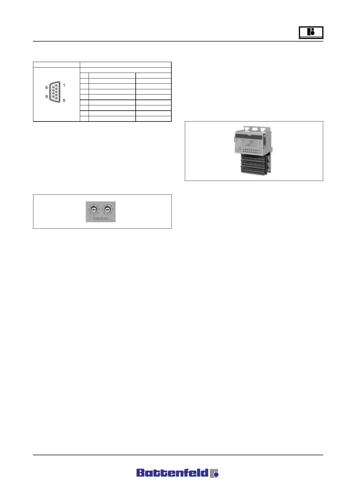
RS 232 interface
The non-isolated RS232 interface is used for
programming the central unit or the signal is
transferred to the disc drive and the printer
interface at the control cabinet.
5.4.4 CAN CP476 node number switch
The CAN node number is adjusted using the two
HEX switches.
The switch positions can be determined at any
time with the aid of the user program. The
switch position is only registered by the
operating system at start-up.
UNIROB-B2 switch position for Node number 1
• RIGHT ”0”
• LEFT ”1”
R8B2_029.JPG
Positions 00, FD, FE and FF are reserved for
special software programming functions. (not
required for standard operation)
5.4.5 Digital Input/Output module
DI439.7 Digital input module – 16 inputs, 24 V
DC
Features:
16 digital inputs
24 V DC input voltage
1 ms input delay
PCS control-to-load isolation
All inputs can be sink or source-connected.
The UNIRON-B2 system uses a sink RC circuit
(refer to circuit diagram on page 14).
R8B2_030.JPG
Interface
1NC
Reserved
2RXD
Receive Signal
3TXD
Transmit Signal
4 + 5 VCD/max. 500 ma
Panelboard power
5GND
Ground
6NC
Reserved
9-pin 7 RTS
Request To Send
DSUB plug 8 CTS
Clear To Send
9NC
Reserved
User interface RS232
Connection configuration
RS232
R8B2_GB028.XLS