A: R82GB0EA.PMD
B: R82DE0EA.PMD
E: 170403 /T. Wenger
G: 020403 / TCS
Section - 5
Page - 4
Assembly and Operation
?
R8B2_014.PDF
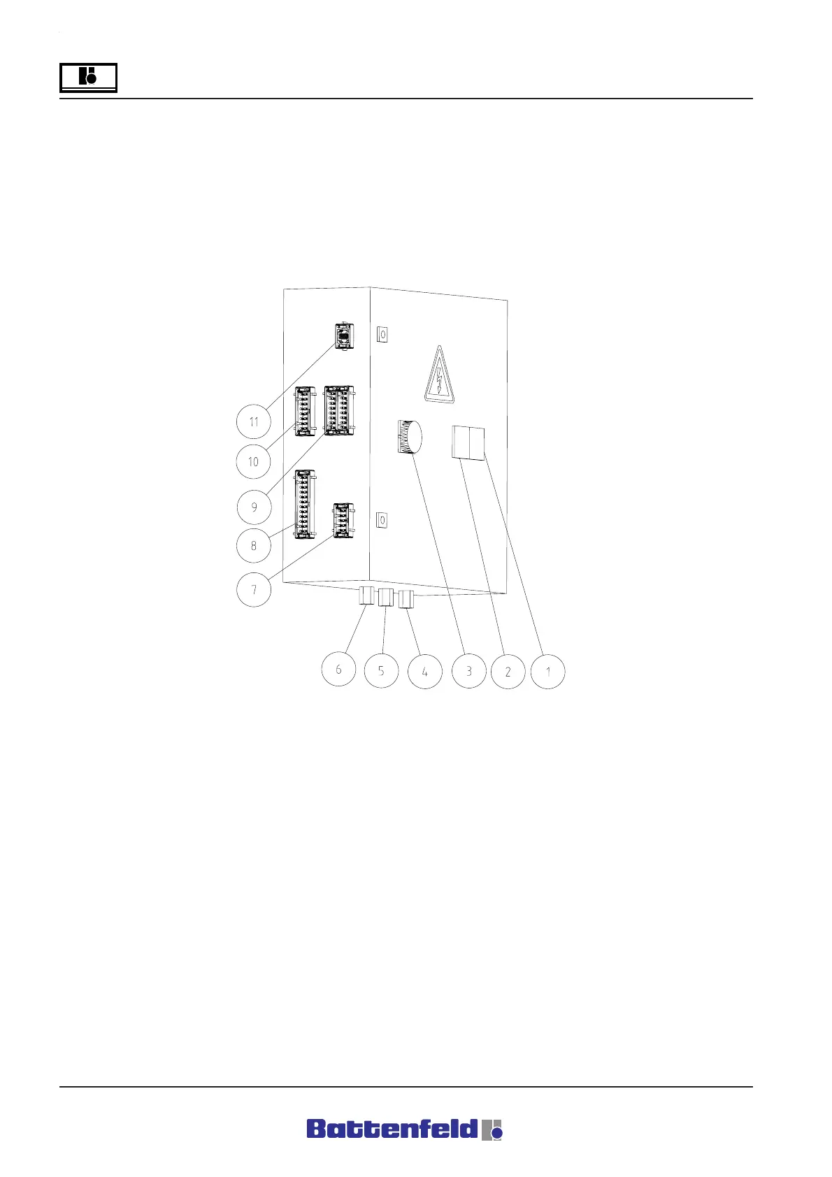
5.3.2 Control cabinet
The control cabinet is located near the robot
system. It must be mounted in an easily
accessible position.
1 Socket
2 Printer interface or floppy disc
DSUB9
3 Main switch
4 Conveyor belt cable gland
5 Peripheral cable gland
6 Power supply (3x400V) cable gland
7 HAN_E plug, power supply connection
3x400V ACOPOS servo booster
8 HAN24 operating door interface
9 Injection moulding machine interface
EUROMAP12 HAN32
10 HAN16_E plug, 24 V DC power supply
for Terminals 1, 2 and CAN
11 HAN6 manual control panel with 24-pin
contact unit
Attention!
Refer to the circuit diagram for details of the
individual plugs!



 To Next Page